
Mounting and nodal offsets
When tracking a camera, the actual point we want to track is called the nodal point of the lens. This point is usually somewhere between the front and back elements of the lens, and it will tend to move along the optical axis as we zoom in and out. For some box lenses, the nodal point may be outside of the physical lens and may move by several metres over the zoom range. If we can make our tracked virtual camera replicate the position and rotation of the nodal point of the real lens, we will achieve good tracking.
Some tracking systems send the nodal point in their data. These are typically tracking systems with lens values baked in e.g. Stype and Ncam. In these cases, we apply the received nodal point position to our virtual camera. Other systems vary in what position they send. In some cases it may be the position of the camera mounting plate or pan pivot poin, while others may supply the position of the camera's sensor (CCD). Some systems send no position at all, but provide information about how the various joints of the camera mount are rotated (Cranes and PTZ heads).
It is very important that the user identifies what position the tracking system is sending. When we know what we are receiving, we can apply the correct offsets in order to track the nodal point of the lens as the camera moves.
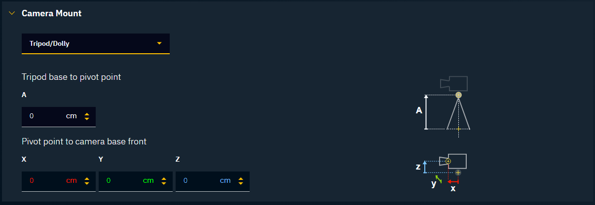
Tripod/Dolly
A Tripod or Dolly camera mount will typically give us two rotations: Pan and Tilt. The first thing to identify is the pivot points for these rotations. When measuring mounting offset for a PTZ, we always measure the distance to the tilt pivot point. This is dimension A. For the X-axis mounting offset, we measure from the pivot point to the front of the camera, X. For the Z-axis, we measure from the height of the CCD sensor to the pivot point, Z. The CCD sensor position is usually marked on the side of the camera. If no marking is visible, measure the center of the lens vertically. It is recommended to mount a camera without any sideways offset from the pan pivot point. If there is an offset, use the Y-direction mounting offset to account for that, Y.
Camera crane
In a typical camera crane setup, the tracking system will send the rotations of the various joints. It is the user's responsibility to measure and input the correct lengths for all the sections of the crane. Use the illustrations in the user interface to insert the correct lengths in the correct place. The mounting offsets will be inserted in the same way as with a Tripod or Dolly.

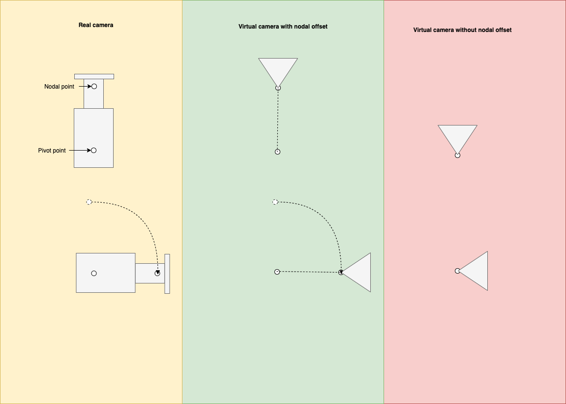
Nodal offset and mounting offsets: how they intersect
The nodal offset and X-direction mounting offsets both do the same thing: they move the virtual camera forward in the direction the camera is looking. This means that adding either of these offsets will cause the virtual camera to move in a larger circle when panning or tilting the camera. The biggest difference between the two is that a mounting offset is static, while the nodal offset will change when the lens is zoomed.
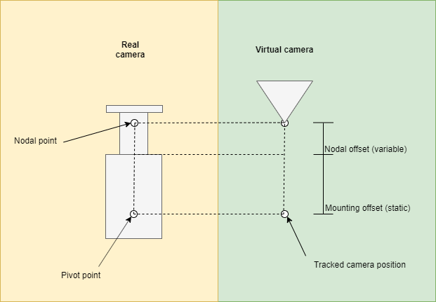
The nodal offset of a lens is determined by the characteristics of that lens. It will, therefore, be a parameter found in the lens file, along with the rest of the lens parameters. Different lens calibration methods will define the nodal offset from different locations: it can be defined from the CCD location, or from the front of the camera. That means that we must define our mounting offset to different locations depending on where it is defined in the current lens file. It is not usually possible to know this, but that is not a problem as long as the nodal offset is adjusted as part of the tracking calibration.