This panel is available when using an XR license
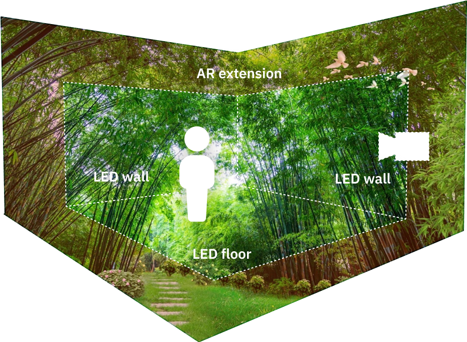
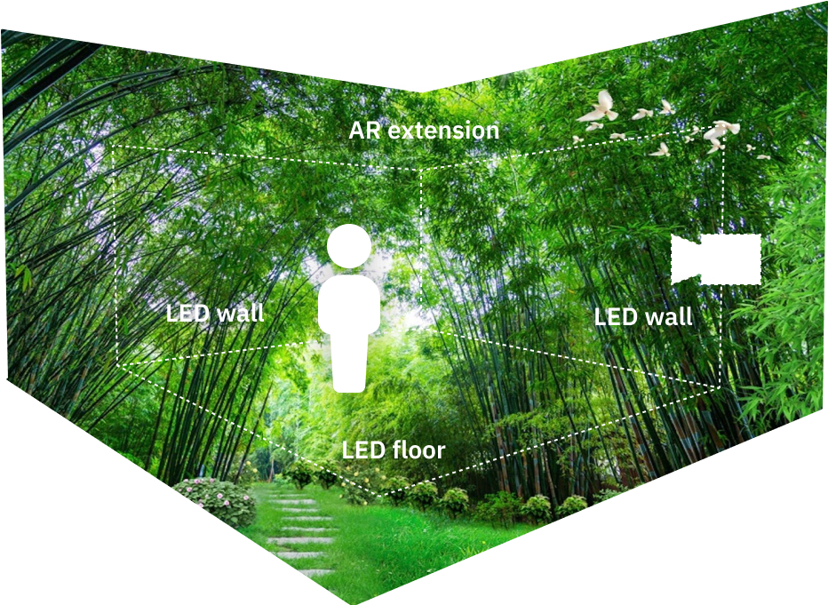
When adding a virtual set extension to an XR setup, matching the colors of the LED walls to the AR graphics manually is tedious. A variety of components in the video chain have an impact on the output colors
-
the XR render machine
-
the Display Processor for the LED wall
-
the LED wall itself
-
the on set lighting
-
the camera
-
the AR render machine
The color matching panel does the whole calibration for you. Just follow the steps listed below.
Calibration
Prepare for calibration
For the calibration to be as accurate as possible make the following preparations to your
Lighting
-
Set up production ready stage lighting
-
Set up production ready ambient lighting
Camera(s)
-
Disable automatic white balance
-
Disable dynamic aperture/exposure
-
Set accurate black/white balance
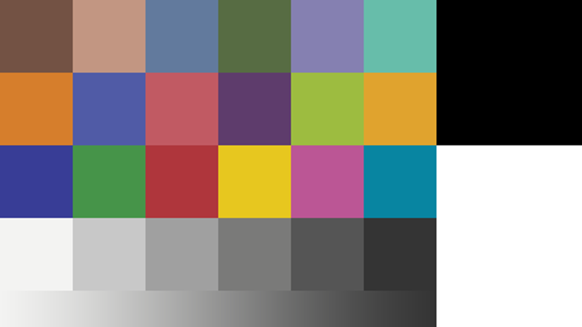
To help you calibrate, show a test pattern on the output of all XR machines selected in step 2 and check the rendering on the AR machine camera input.
The white level will be automatically detected with a notification indicating the percentage of the optimal level.
Frame
-
Aim the camera at the center of the LED wall
-
Zoom in so the camera frames only the LED wall
-
Be out of focus (blurred image) -
Lock off the camera head
Click "Get frame sample" to check the bounds of your frame. The calibration process only samples data within the bounds.
Show settings
Compositing color space needs to be set to Linear space in SETUP > Show > Show settings.
Specify your setup
-
Select the main AR machine (single select)
-
This machine will be used in the calibration process filming the LED wall
-
-
Select your XR machines (multi-select)
-
These machines will be used in the calibration process for displaying. To only use specific machines during the calibration process, enable the checkbox below and select a subset of machines.
-
-
Optionally: Filter which machines to display the calibration pattern on (a series of flashing lights) during the calibration process.
-
The generated AR color profile will be automatically used by any machine running AR
-
The generated LED color profiles will be assigned to the selected XR machines
Configure process
-
Specify which calibration steps you would like to run (see below)
-
Set the sample number of the profile
-
Larger values can improve the result, but they increase the time for analysis significantly. Higher quality LED walls require fewer samples. Values between 7 and 15 usually give good results.
-
-
Start the calibration
Calibration steps
|
Calibrate LED wall |
optional |
|
|---|---|---|
|
Color match AR to LED wall |
main step |
|
During color analysis
-
Do not move the camera
-
Do not occlude the camera view
-
Do not change the lighting
Possible warnings during color analysis
|
Message |
Suggestion |
|---|---|
|
Could not determine the display's latency |
Ensure that the camera is aimed at the display properly and that a valid video signal is present. |
|
Detected latency is X frames |
This happens when latency is more than 30 frames. Consider checking the delay values in Director and that the camera is aimed at the display properly. |
|
CAUTION camera exposure too low |
Increase camera exposure and restart calibration. |
|
CAUTION color gamut clamp |
Check the color format to match the LED’s wall gamut capacity and restart calibration. |
|
CAUTION sync issue during calibration |
May happen on temporary higher latency (e.g. high GPU load in Editor). Check your setup or enable +15 frame delay option and restart calibration |
After color analysis
Using the color grading panel in combination with color matching will deliver varied results. Here are our recommended use cases.
|
|
3D Graphics |
Video |
Final output |
|---|---|---|---|
|
XR machines |
OK, if color grading is the same across machines. |
Not applicable |
Not recommended |
|
AR machines |
Not recommended |
OK |
Making changes to, for example, the video white point should be done through the Color grading panel and not on the camera itself.
Vignetting
Using the Effects panel might be needed to accommodate possible vignetting effect depending on the lens characteristics. Vignette intensity should be increased in oder to extend the darkness effect on edges when appropirate.
Profiles
This advanced tab allows to
-
see debug profiles
-
manually reassign the generated
-
AR profiles
-
LED profiles (AKA XR profiles)
-
-
show a Chromaticity diagram for any selected profile
-
unassign all AR & LED profiles selected
Default state (before Calibration)
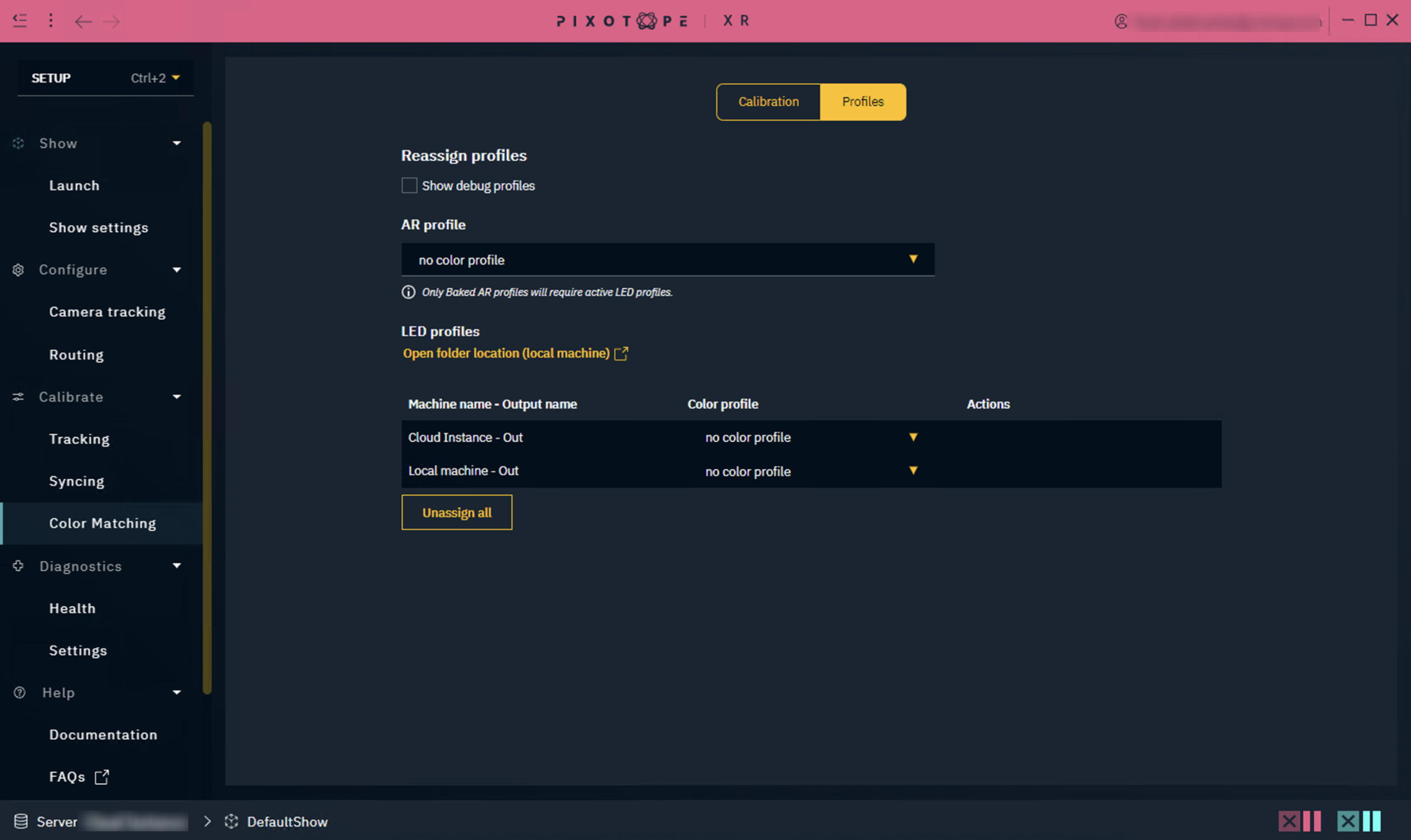
Once Calibration has occurred, the profiles will be automatically assigned to the corresponding fields.
Chromaticity diagrams
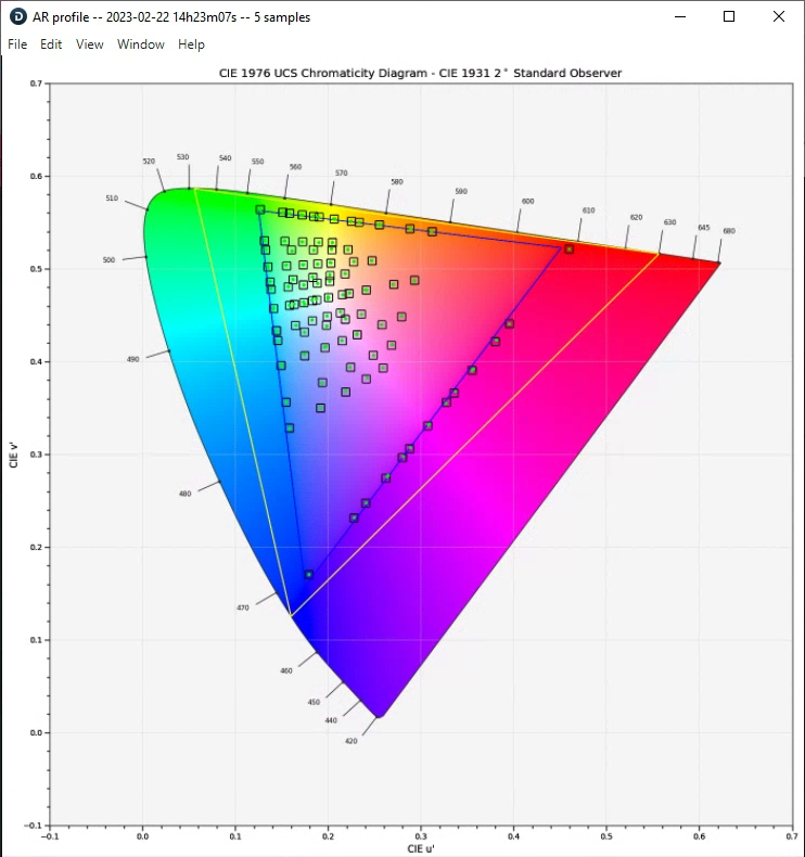
The purpose of this diagram is to visualize color accuracy. In addition, it can help detect if something went wrong during a long calibration process (eg. LED wall occluded by something onset).
How to read this chart:
-
Yellow triangle is the area corresponding to Rec.2020 color gamut
-
Blue triangle is the area corresponding to Rec.709 color gamut
-
Blue square is the theoretical position of the color patch in the Chromaticity diagram
-
Green dot is the position of the color patch in the Chromacity diagram after it is displayed on the LED screen, and was captured by the camera routed to the AR machine
Ideally the green dots will be in the center of the blue squares, but this is not always the case due to imperfect color accuracy of the LED screen. Pure black level is rarely encountered, and LED walls have gamut limitations that prevent the color patch to be shown on gamut boundaries (the blue triangle).
.png?cb=5ba569609a77656e89a1c8b2c1110cdd)
AR profile validation
The state of the validation text changes depending on the type of AR profile selected, and the corresponding LED profiles assigned in the table below.
A Baked AR profile is created when both calibration steps (Color match AR to LED wall & Calibrate LED wall) are enabled when calibrating.
If you have created an AR profile where only Color match AR to LED wall was enabled → Do not assign any LED profiles below
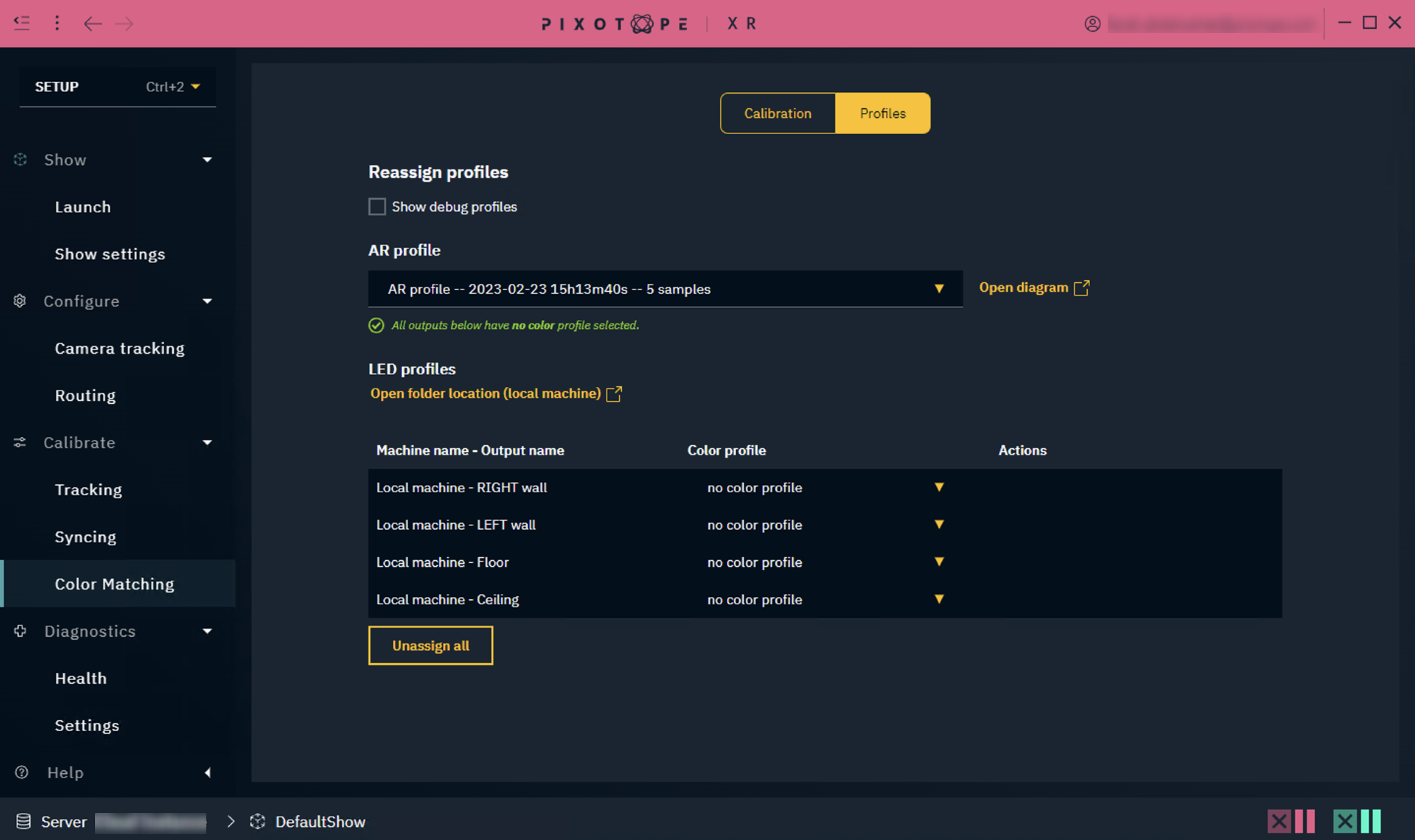
If you have created an AR profile where both Color match AR to LED wall & Calibrate LED wall were enabled → Assign the corresponding LED profiles to all outputs below
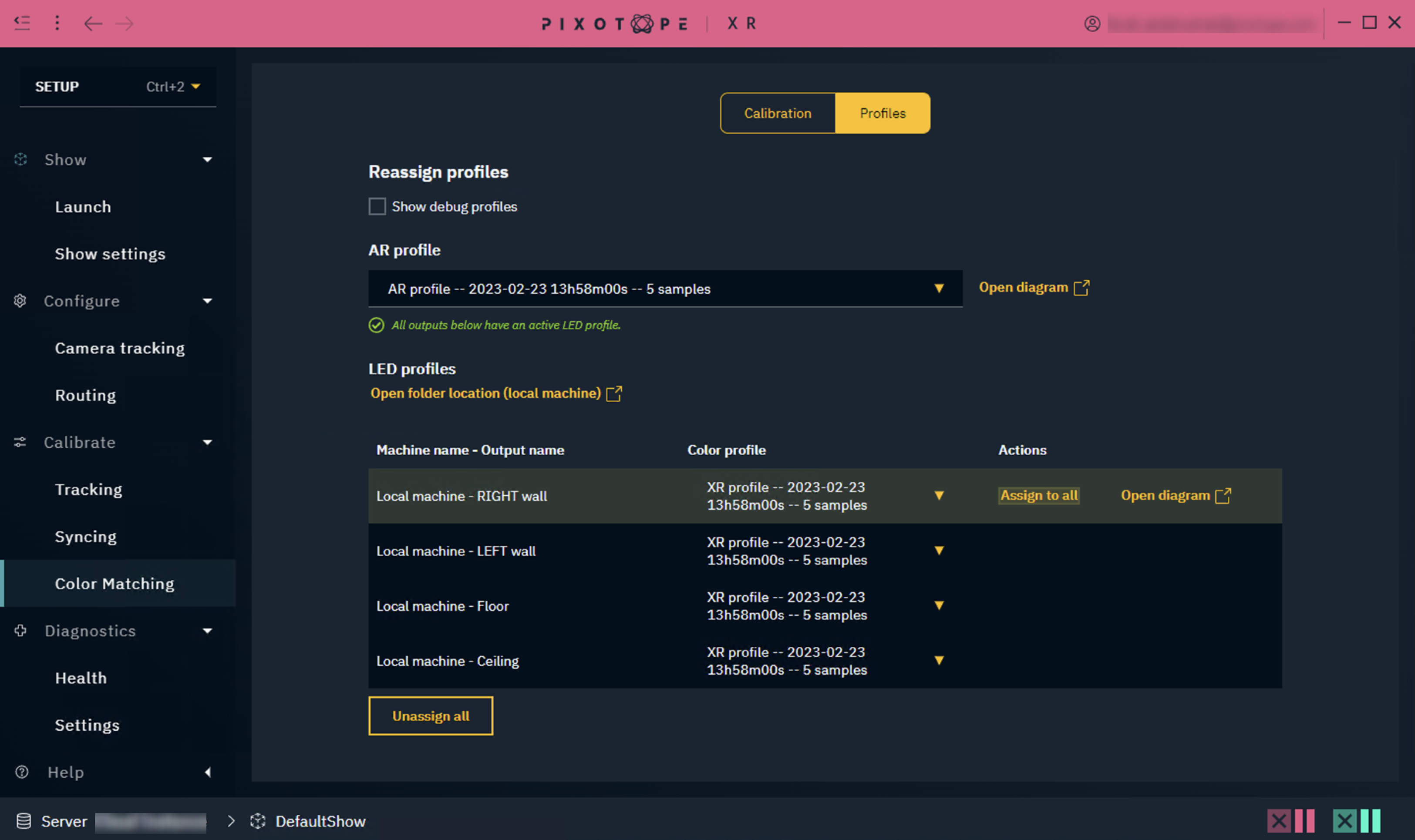
The validation text will keep track of which AR profile you have active, and update based on its specific criteria.
Unassign all will clear both the AR and LED profiles selection.
Profiles storage
The profiles can be found on all connected machines:
...\Pixotope\[Version Number]\Services\VideoIO\ocio-configs\Pixotope XR Calibration
-
AR and LED/XR profiles can be found in the above path as
.cubefiles -
Chromacity diagrams can be found in the above path as
.pngimages