With DMX we have a way to tie physical and virtual lights together. This will create more seamless environments for mixed reality content.
How to control a physical and a virtual light with the control panel
Our Art-Net/DMX implementation is currently able to take any value from Blueprints and forward it as a byte array to individual channels in a DMX universe. The system supports full daisy-chaining and control of multiple fixtures.
Physical light setup (used in our example)
XLED HD (16-bit) fixture from Bright Group (RGB-controlled).
-
Select 3-channel mode, RGB
-
allows the fixture to control other elements (dimming etc.) internally
-
-
Add a "W"-slider multiplier for additional control of matching the virtual lighting
Wiring
-
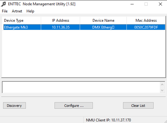
Pixotope -> Enttec MK III Art-Net to DMX unit sending to XLED HD configured on fixture to DMX channel 1 (in the example using Universe 0)
-
Pixotope needs to be configured to same IP range as Enttec unit in Networking
Pixotope setup
-
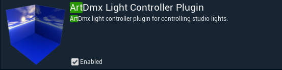
Check that the ArtDmx Light Controller Plugin is enabled (shipped with Pixotope 1.3)
Blueprint setup
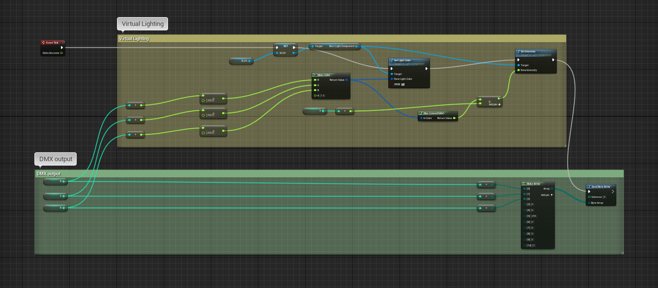
This is the complete graph we are going to build. It controls one fixture as well as a matching virtual light.
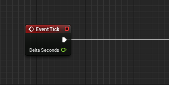
Event tick graph
-
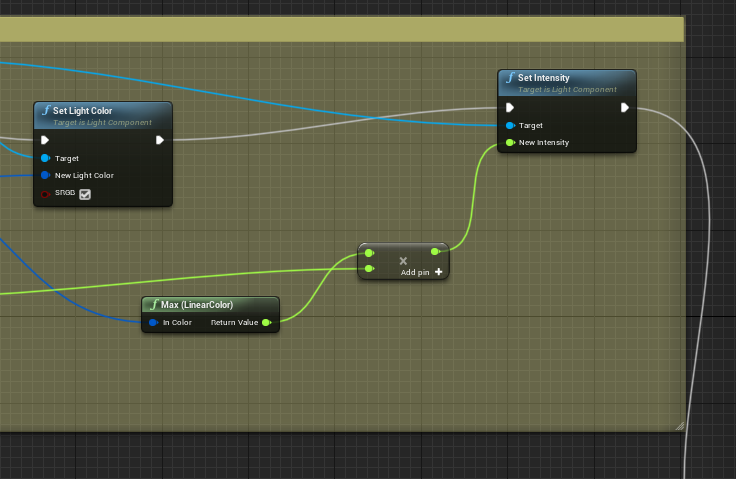
The top part of the graph is the control of the virtual light in the scene
-
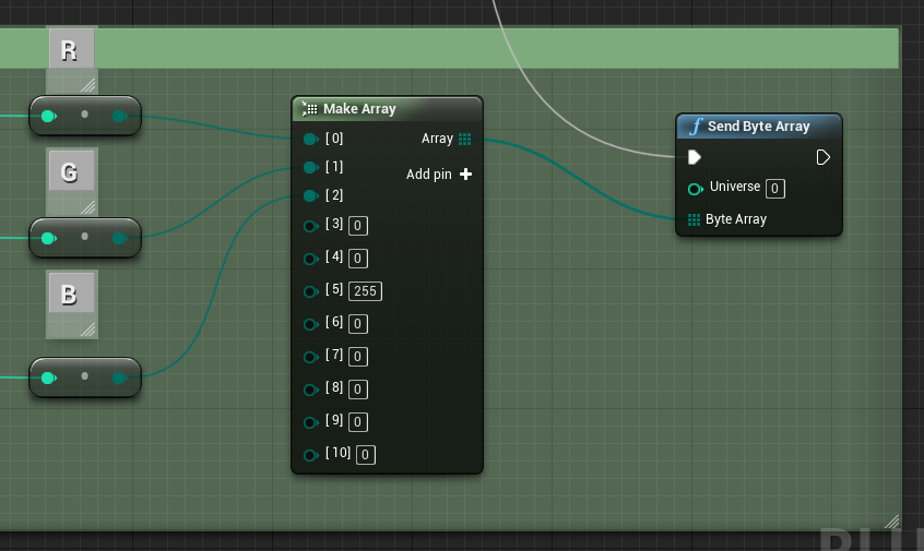
The bottom part shows the variables being sent through a byte array indicating the DMX channels of the fixture, then passed to the correct DMX universe
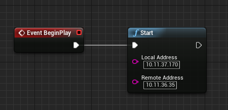
Event BeginPlay graph
This part starts the Art-Net connection.
-
Start LightManager node
-
The Local Address is the local IP, and Remote is the destination for Art-Net
-
Create new Actor BP

-
Add the Blueprint to the level
-
Add 5 variables to the Blueprint
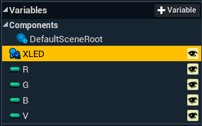
-
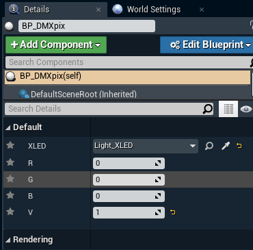
The R G B V variables are set to an integer type.
These are the connection endpoints used at runtime in the control panel from Director -
The top variable is of type rect light object reference. This is a light in the scene that we add to the Blueprint
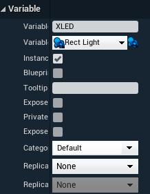
-
The rect light in the scene is added to the Blueprint variable in the level itself
-
-
Create a color from the incoming variables for R G B and pass it to the light reference (rect light variable object)
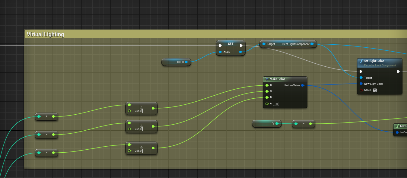
-
Use the "V" variable as a multiplier to balance the virtual light closer to the real light if the intensity needs finer adjustments at runtime
-
Pass the R G B integers (in this example we are passing 0-255) to a byte array using a Make Array node. This adds the channels matching the inputs of your physical light fixture. The output of the Make Array node gets passed to the Send Byte Array node (from the DMX plugin) and passes it to the corresponding DMX Universe
-
Connect everything on tick
-
This will allow the BP to update when we change the slider in our control panel on every tick
-
Control panel setup
-
Create a new control panel in Director
-
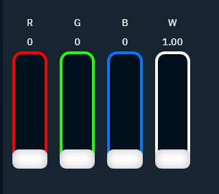
Add 4 sliders for the R, G, B and V values
-
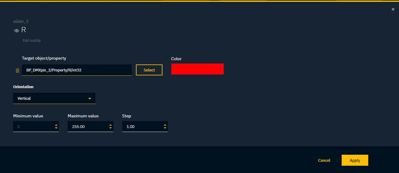
Right-click the R slider to edit it
-
Set a label "R" and turn on its visibility
-
Set a color so it stands out
-
Set the min, max and step values of the slider
-
-
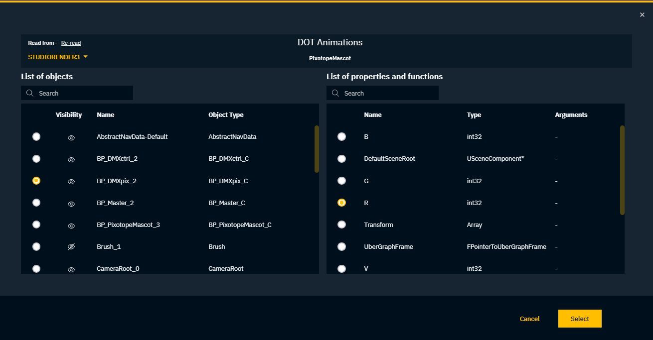
Click "Select" to set the target object/property which will be controlled by the slider
-
Select our Blueprint actor on the left side, "BP_DMXpix"
-
Select the R property on the right side
-
Click "Select"
-
Repeat these steps for the other slider widgets
-
Save the control panel
The sliders in the control panel now control both the virtual as well as the physical lights via DMX.