Without Pixotope Tracking, the Digital Twin has to be created manually.
For creating an automatic Digital Twin using Pixotope Tracking check out Calibrate XR alignment
Create manual bodies
Create one Manual Twin body for any LED body. A body is a continuous LED surface. A curved LED wall with an extra LED floor would, for example, be 2 separate bodies.
-
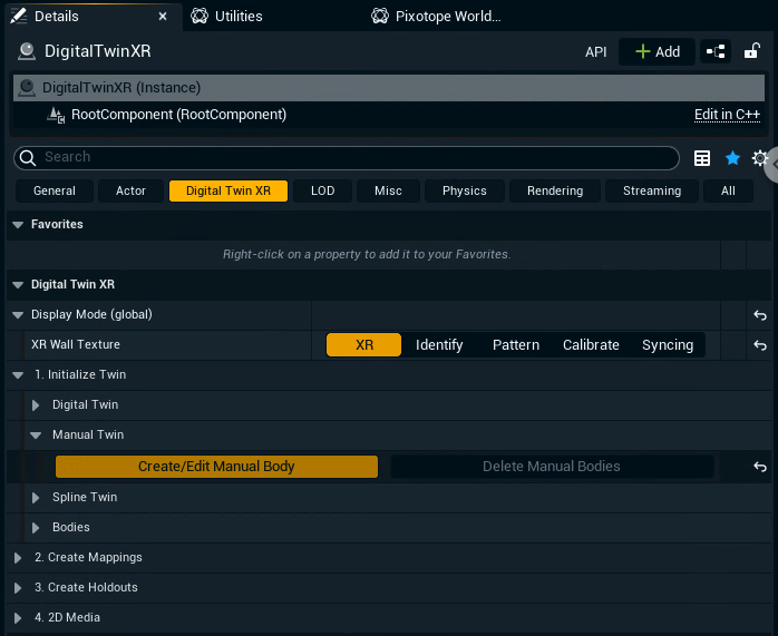
Select the Digital Twin XR actor and go to its Details panel
-
Click on "Create/Edit Manual Body" inside 1. Initialize Twin > Manual Twin
-
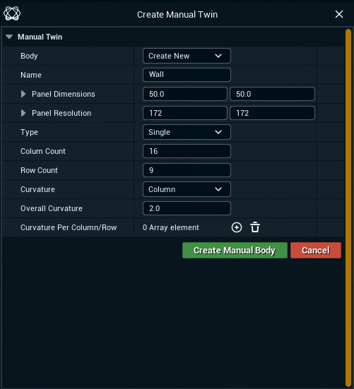
Optionally: Choose a name
-
Specify the panel dimensions in
cmand the panel resolution inpixel -
Select the Type (Single or Cube) and specify its options
-
Click "Create Manual Body"
Single type
Single type
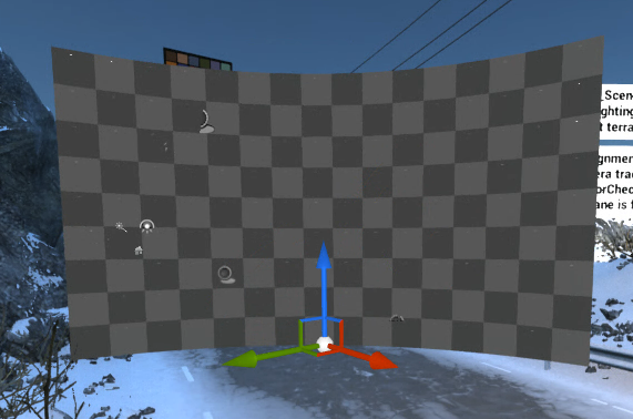
A single wall/body with optional curvature is created.
-
Specify the Column and Row Count
-
Specify if the wall should be curved along the Columns or Rows
-
Optionally: Set an Overall Curvature
in degrees
OR create an array and specify the Curvature Per Column/Row individually
Cube type
Cube type
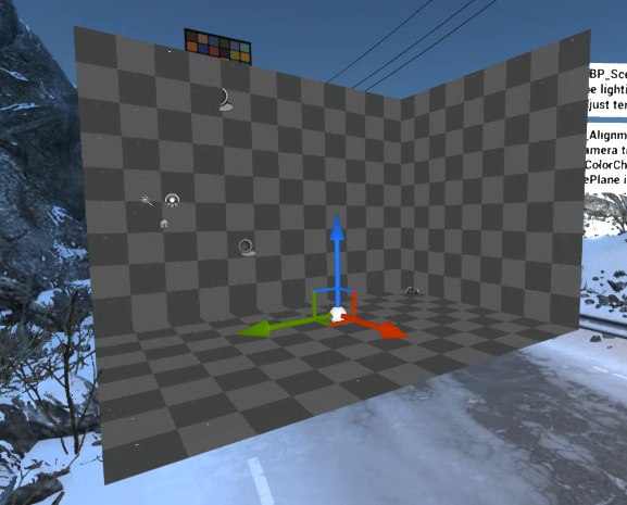
Flat walls/bodies are created placed on a cube.
-
Specify the Width, Height and Depth of the Cube/Walls
-
Select which sides of the Cube should be created (Floor, Ceiling, Left, Center, Right, Back)
Convert any 3D mesh
Convert pre-made mesh
You can convert any mesh, or multiple meshes, into manual bodies/a digital twin.
If your mesh is properly measured to represent your physical LED setup (from a CAD drawing or .obj file for example), the setup should only take minutes.
One XR wall is created for each quad of the mesh.
Generate XR walls
-
Import mesh(es) into your level
-
Right click the selection
-
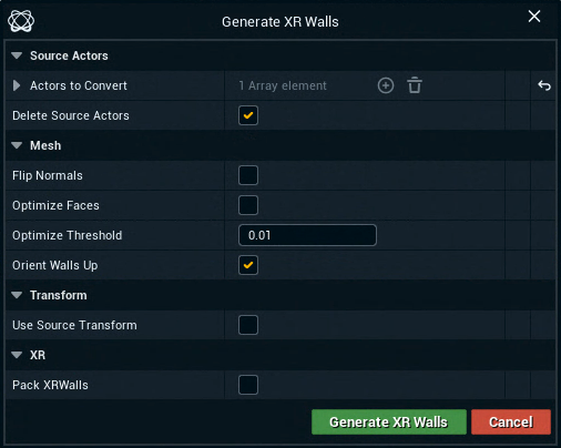
Select "Generate XR walls from Actors"
-
Use the following menu to fine-tune the generation
-
if your XR walls are facing the wrong way, toggle “Flip Normals”
-
“Optimize Faces” will collapse faces that share vertices and have a similar normal direction. See the following gif for an example
-
"Optimize Threshold" is for the normals' value. By default this value is almost touching, but can be manipulated if the normals are at all shifted
-
Pack XR walls can stay disabled as we will map them later
-
Merge walls (optional)
To reduce the wall count you can manually select XR walls and merge them together.
-
Select 2 or more XR walls and right click
-
Select "Merge XR walls"
Convert to Digital Twin
-
Select all XR walls and right click
-
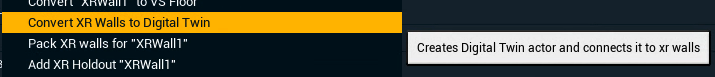
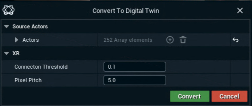
Select "Convert XR walls to Digital Twin"
-
Increase the Connection Threshold to connect XR walls which are close to each other into a single body
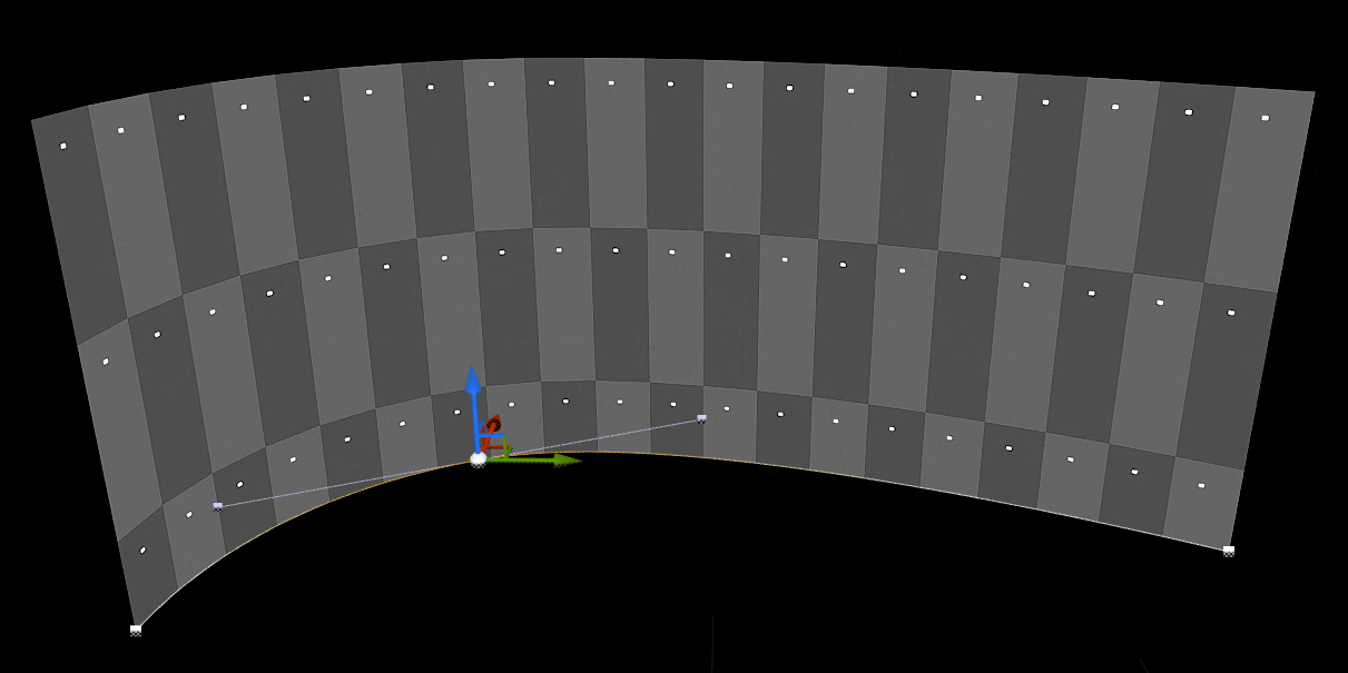
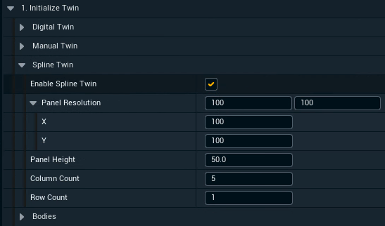
Spline twin
Spline twin
Use a spline as guide for generating XR walls
-
Click "Enable Spline Twin" in the 1. Initialize Twin section
-
A Spline component gets added to the DigitalTwinXR actor
-
-
Adjust the setting
-
Adjust the spline
-
Alt-Drag a spline point to create additional points
-
Create mappings
-
Click "Create All Mappings"
Learn more about how to Create mappings
Position and scale the Manual Twin
-
Position and scale the Digital Twin XR actor to align with the real world LED walls
-
Enable WYSIWYG to make aligning the walls easier
-
Check your alignment using an AR machine
Learn more about how to Check your alignment
Create XR holdouts
-
Click "Create Holdouts" in 3. Create Holdouts
Learn more about how to Create holdouts
Set up for 2D Media playback
Learn more about how to Playback 2D media on the LED wall