This document is a short guide on how to install and use external lens encoders with Pixotope Tracking. These encoders will read the position of zoom and focus rings and forward the information to the tracking system, so it can calculate the corresponding optical parameters based on the respective lens calibration.
Pixotope sells two kinds of external encoders:
-
Contact-free encoders with magnetic tape and are not dependent on gear specification of the lens manufacturer. The magnetic tape needs to be stuck to the focus or zoom ring on the lens
-
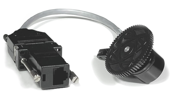
Gear encoders come with three different cog wheels for different teeth sizes (Canon, Fujinon and prime lenses)
The sensors will adapt to any given lens. They detect the zoom/focus ring range by rotating them fully at the start of the tracking software. They forward one balanced serial signal to the tracking workstation for zoom and focus individually.
.JPG?cb=e5b485bcf9e7979324f081f5789f1612)
1 Part List
1.1 Package Contents
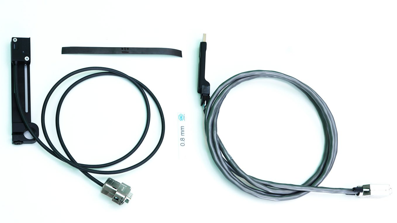
The encoder package generally consist of the following hardware parts for each zoom and focus (see Illustration 3):
Contact-free Encoders:
-
A contact-free sensor with build-in short serial cable output to 9-Pin D-Sub (RJ45 adapter included)
-
An aluminum mount to attach the sensor on a 15mm accessory rod with various angle and height
-
A band of magnetic tape for fixation on the zoom/focus ring
-
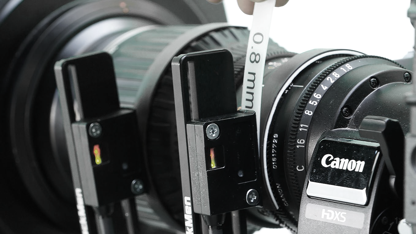
A plastic stripe with 0.8mm thickness to find the correct distance between sensor and tape
-
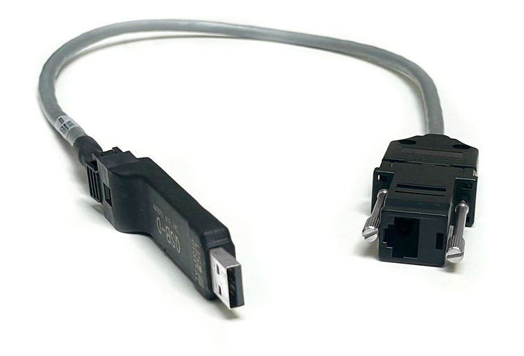
A USB-converter to connect the serial line with a workstation, with attached 9-Pin D-Sub connector (RJ45 adapter included)
Gear Encoders:
-
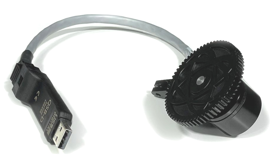
A gear encoder with build-in short serial cable output to 9-Pin D-Sub (RJ45 adapter included)
-
An aluminum mount to attach the sensor to an existing screw hole in the lens (Illustration 16)
-
An aluminum mount to attach the sensor on a 15mm accessory rod with various angle and height (Illustration 15)
-
Three cog wheels with different teeth sizes (Canon, Fujinon and prime lenses)
-
A USB-converter to connect the serial line to a workstation (RJ45 adapter included)
1.2 Additional Parts
The external encoders will be integrated into an otherwise complete Pixotope Tracking system. For completion of the lens connection, the following parts will be needed:
-
An ethernet cable between sensor output and USB-converter
Please make sure to use a high-quality shielded cable as extension between the two devices!
-
A Pixotope lens calibration file for the respective lens that will be employed. See the Lens file Database and download the file in the Pixotope Cloud.
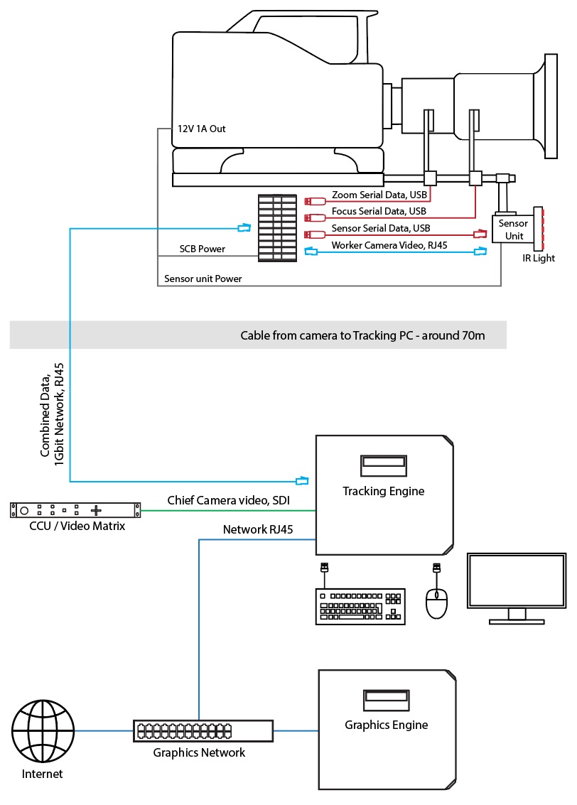
1.3 External Encoders with an SCB
When using external encoders together with a Signal Collector Box, the USB-converters go directly into the USB ports of the SCB. Ethernet adapters and cables will not be needed in this case.
Setup with a Signal Collector Box
2 Hardware Installation
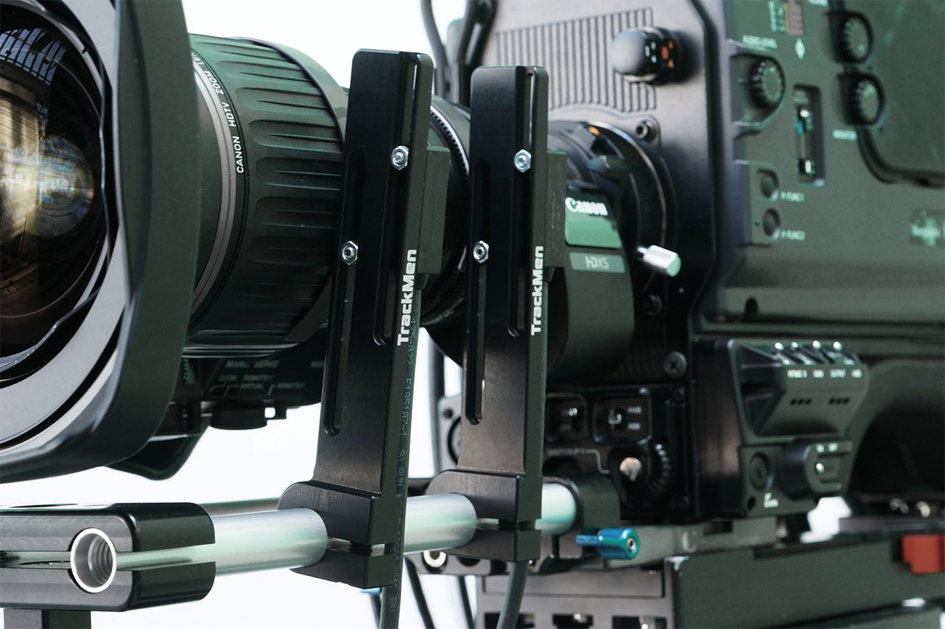
2.1 Contact-free Encoders
-
Fix the Sensor on its mount using both screws and the respective long holes. One side of the mount is countersunk for the nut to fit in. If zoom and focus ring are too close together, it may be necessary or desirable to mount both sensors on one mount, using a longer screw
-
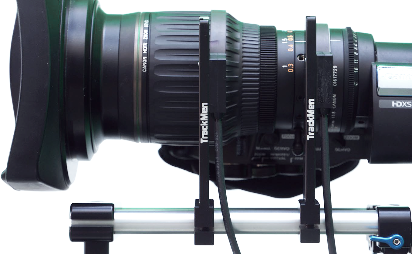
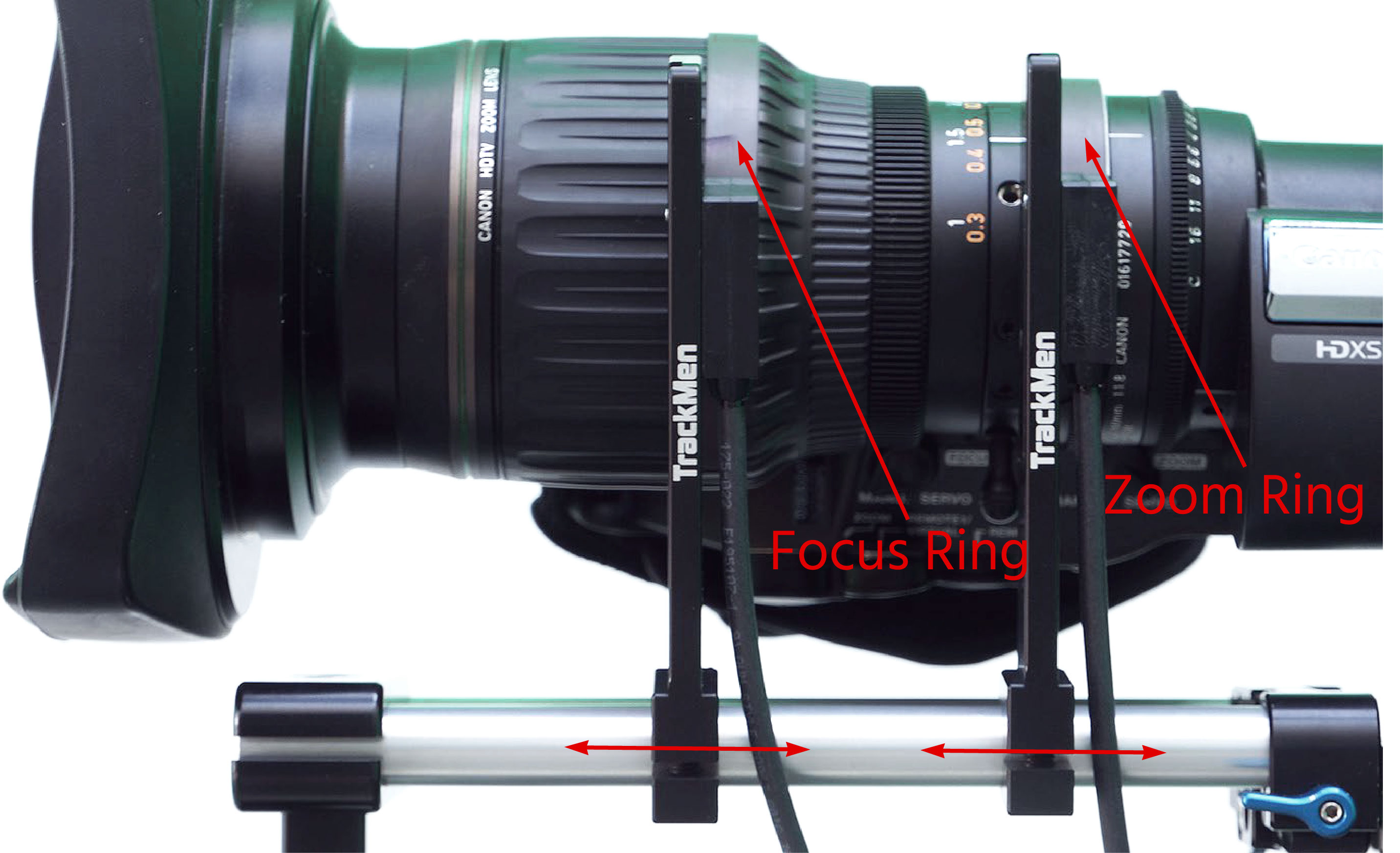
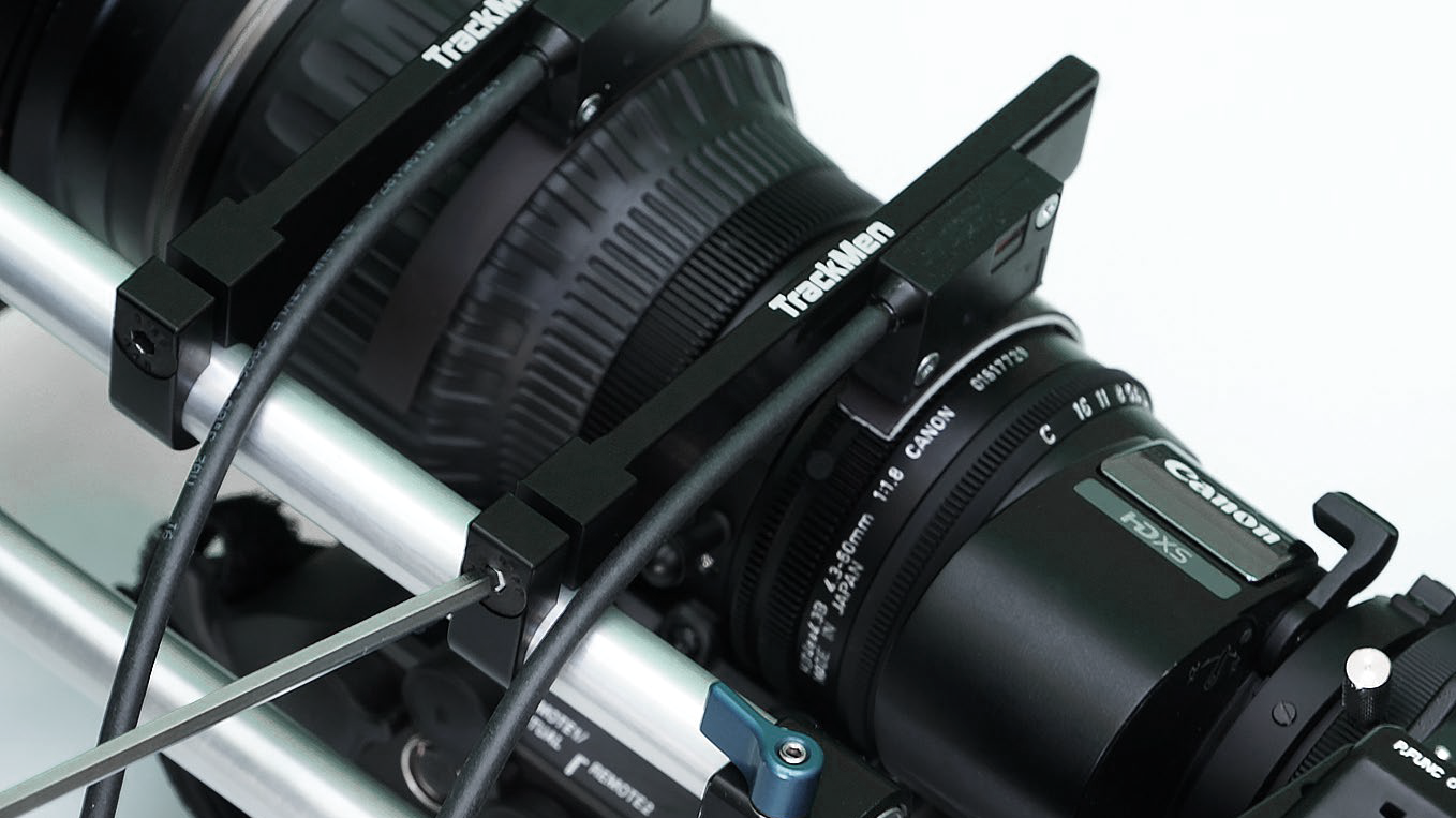
Slide the mount onto the 15mm accessory rod up to the position of the respective ring
-
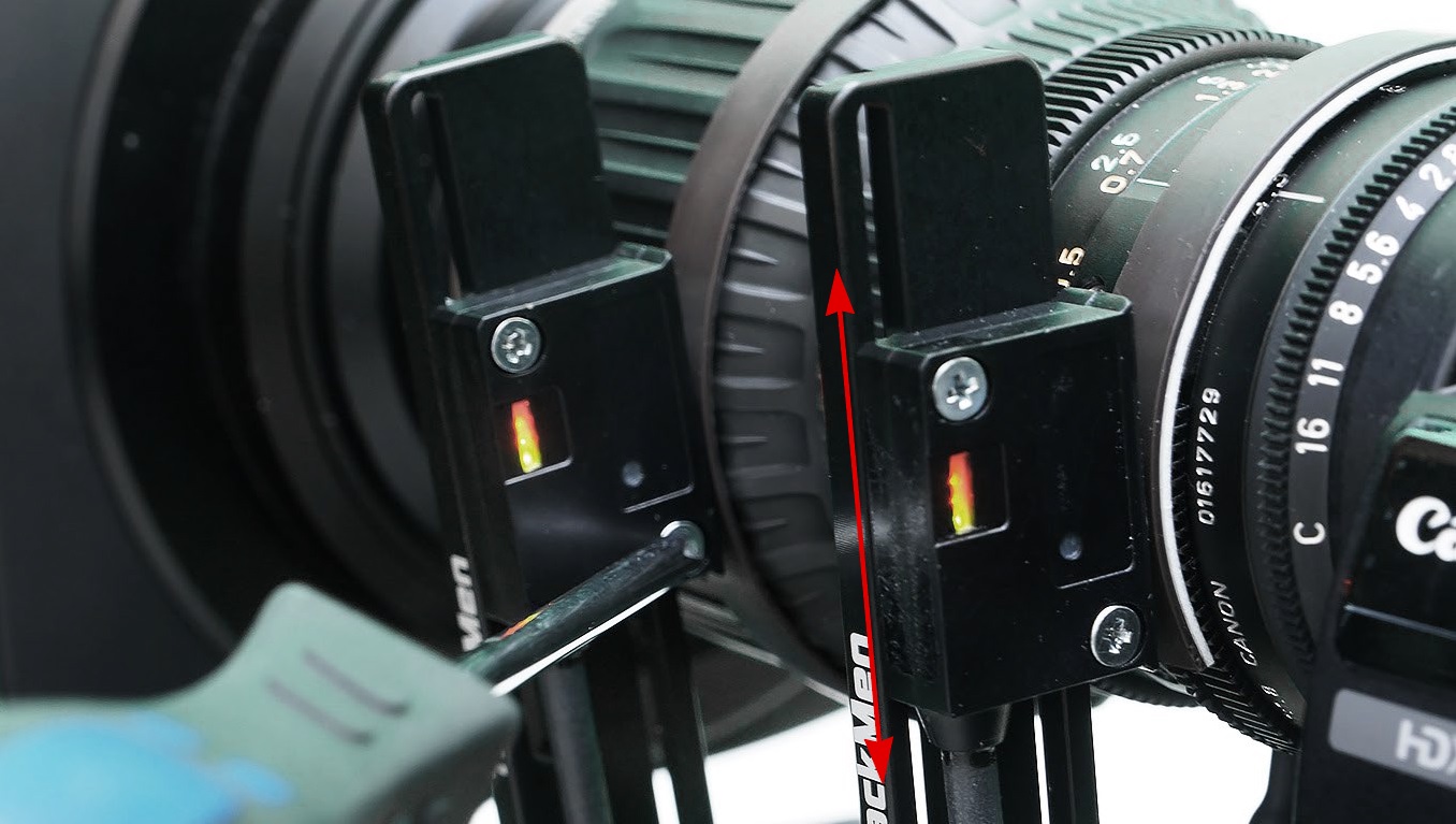
Adjust the height of the sensor using the long holes, so the middle of the sensor is as close to the lens as possible. Fasten the screws firmly
-
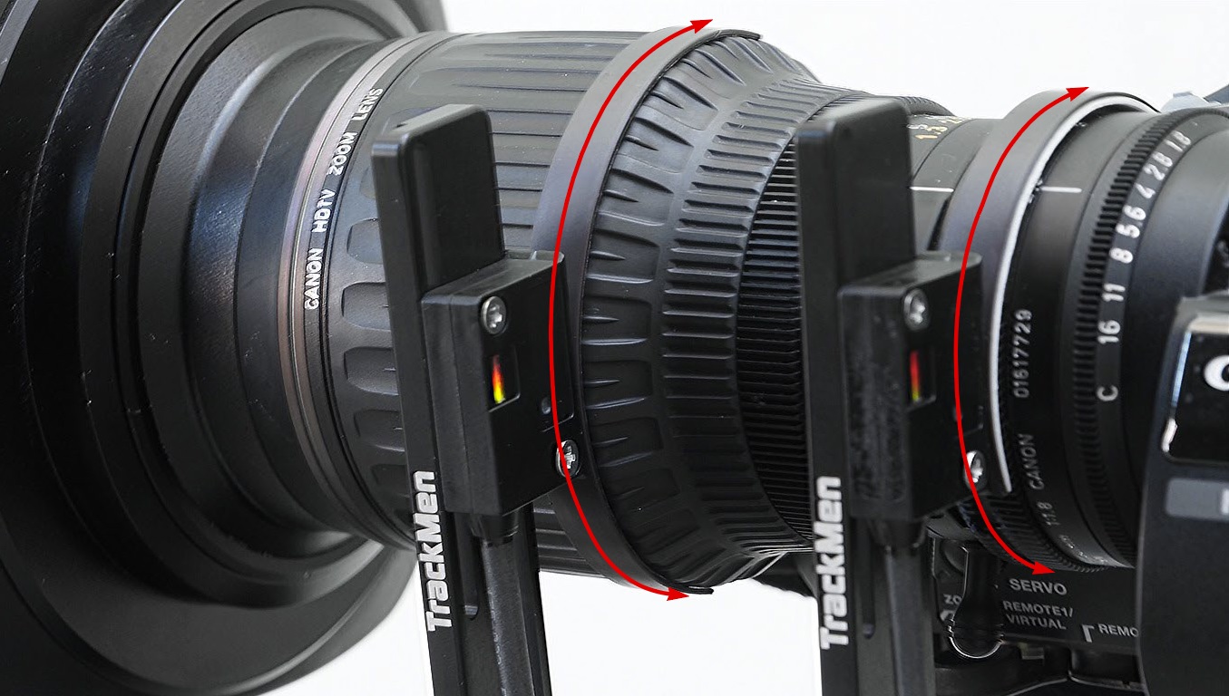
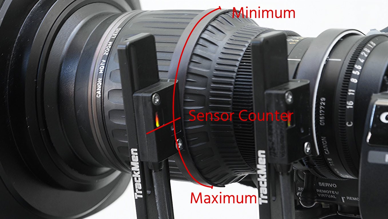
Evaluate the range of the zoom/focus ring that will need to be covered with the magnetic tape: mark the point on the ring that is just covered by the sensor when the zoom/focus position is at wide angle / infinite, then turn it to maximum tele / MOD position and mark the furthest point covered.
-
Make sure the tape can cover the whole range. It may be shortened if too long
If the tape cannot cover the whole range for some reason, think of another way to attach the mount. Maybe using the accessory rod on the other side and having the sensor mounted below the lens, for example.
-
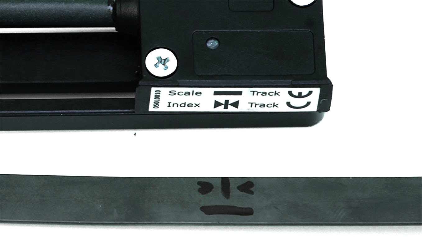
Fix the tape on the lens ring. The direction is important: The tape has two areas: one for the counter marked with a - and one for the Index, marked with a >|<. Make sure the tape is oriented so the
marks fit the corresponding ones on the sensor
-
Adjust the distance between sensor and magnetic tape, holding the 0.8mm plastic strip between them
-
When correct, fasten the hexagon socket screw on the bottom side of the mount firmly. Make sure it can not be accidentally moved easily
2.2 Gear Encoders
-
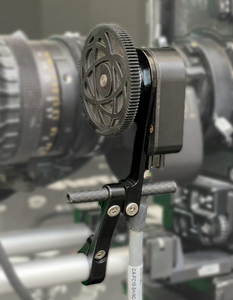
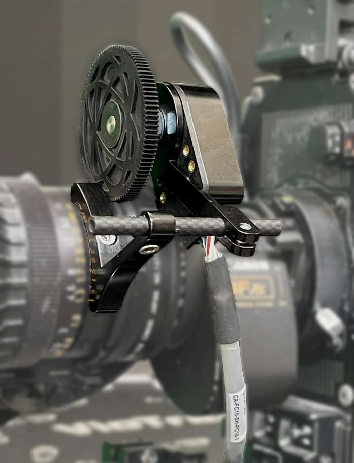
Mount one of the aluminum mounts either onto a 15mm rod or onto the screw hole on the lens itself
-
Connect this mount with the encoder-mount, using the small carbon tube
-
Move the encoder on the tube so that the cog wheel touches the respective lens ring
-
Tighten all screws
-
Connect the cable to the Encoder
3 Handling
The following changes apply to the tracking system when external encoders are used:
3.1 Interface
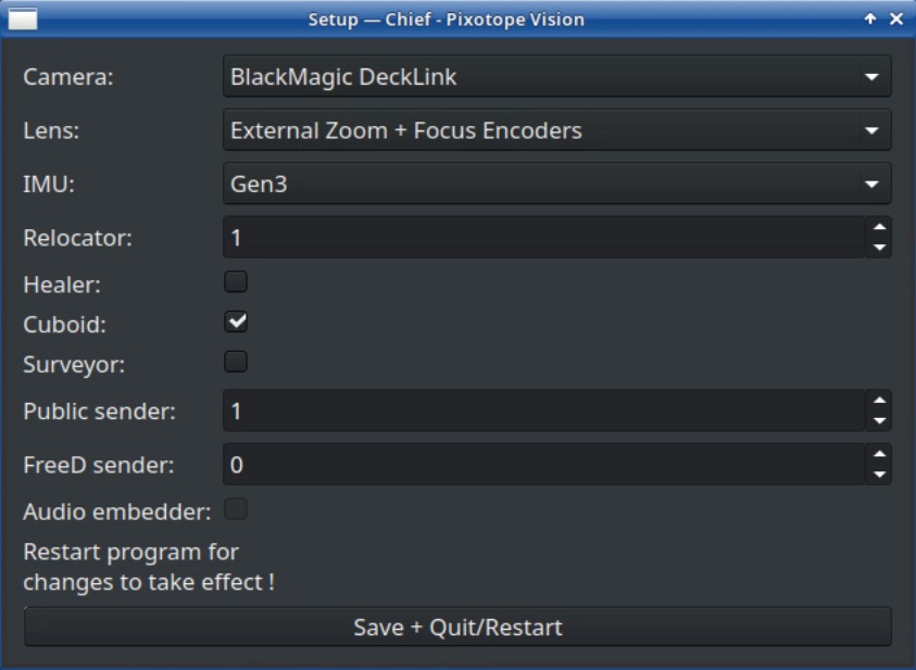
Usage of external zoom and focus sensors will take a slightly different Chief setup than lenses with build-in data output. Select the External Encoder(s) under Lens in the Chief Setup.
When using an SCB select External Encoders via Signal Collector (SCB) and select External Encoder in the Signal Collector software.
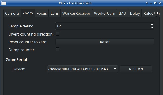
This configuration will bring up two new tabs: Zoom and Focus. Both show the same four options:
Sample delay will set an additional delay for the encoders in milliseconds, in case their timing differs from the rest of the tracking and is not precisely adjustable by using the Lens Delay in the WorkerCam tab.
Invert counting direction will swap whether zooming in / focusing a distance will use rising values or dropping ones. Use this option when you notice that turning the respective ring gets interpreted the wrong way.
Reset counter to zero will set the current value of the data to zero.
Dump counter will show the current encoder values in the System Log as long as it is checked.
Device chooses which USB adapter is used for input.
3.2 Initialization
The external encoders must be initialized each time the Chief gets started. If an SCB is used, they only need to be initialized after an SCB software restart. In order to do so, wait for both system and camera to fully boot and then zoom all the way in and out and focus both MOD and infinite. The system will automatically recognize the detected minimum and maximum value as full range and be ready to work.