1 Preface
The optical camera tracking system GhosTrack makes perfect use of the patented GhostFrame technology. It uses hidden information of GhostFrame LED panels to calculate the pose of the camera.
This means that the setup can be automated and be done within a very short period of time. Ghostrack delivers the highest precision for virtual productions. It allows camera tracking even for closed LED caves, where the backwalls and maybe even the ceiling or floor is covered with LED panels. In such an environment, marker-based optical camera tracking systems or additional sensor cameras for outside-in tracking cannot be used without interference. But the hidden tracking information of GhostFrame turns every LED panel into a reference object for camera tracking. GhosTrack works where other systems fail.
2 Working Principle
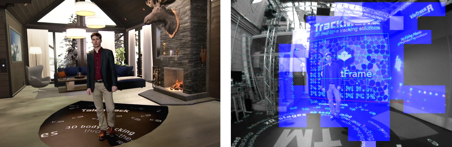
GhosTrack uses the same working principle as Pixotope Vision, but with an enhanced feature to enable it to read a concealed tracking pattern on the LED panels. With the GhosTrack Tigger Box, the sensor unit can be synchronized in such a way, that it only sees the hidden pattern. The pattern itself remains invisible to the human eye and the film camera.
2.1 GhostFrame
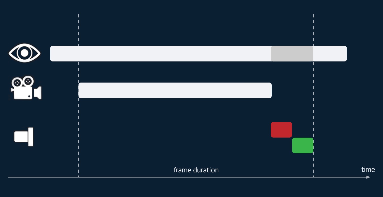
Multiple contents are displayed on the LED panels at the same time. The largest part of the frame duration will be used for displaying the content for the film camera. The length of this part depends on the capabilities of the LED panels. The film camera is then synchronized to this content, so that it sees this content without any loss of quality.
A preferably short part of the frame duration is then used for displaying the tracking reference (see red bar in graphics below). Since the human eye is capable of seeing both those contents, this would normally result in a flickering effect. The solution for this is that the tracking reference is shown twice. The second time inverted (green bar in graphics below) and for the same length of time. This way the tracking reference becomes grey and therefore invisible for the human eye. At the same time this gray slice reduces the saturation of black within the LED image and reduces the contrast; but for the human eye only, the camera image still shows brilliant contrast.
2.2 GhosTrack pattern
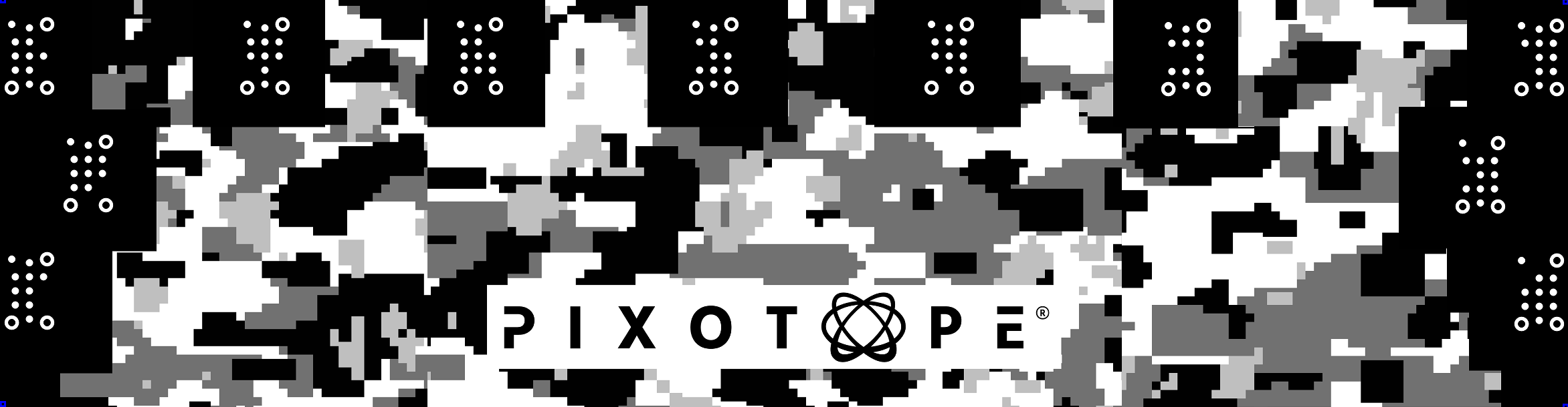
The GhosTrack pattern can consist of both coded markers as well as an irregular pattern. The coded markers enable simple and fast calibrations. The random and irregular part of the pattern provides reliable feature points for the markerless image recognition of the tracking software.
3 Requirements
3.1 GhostFrame
GhosTrack is based on the GhostFrame technology. It has special requirements for the LED panels as well as the processor. For more information on this, please visit the GhostFrame website and scroll down to the required equipment.
GhostFrame - Add Green Screen, Hidden Tracking, and Multiple Sources | GhostFrame
3.2 Trigger Box
GhosTrack uses the same hardware as Pixotope Vision with the only addition of the GhosTrack Trigger Box. The Trigger Box synchronizes the sensor camera to the tracking pattern in the LED wall. To do so it requires a genlock signal input. Every tracked camera needs an own Trigger Box.
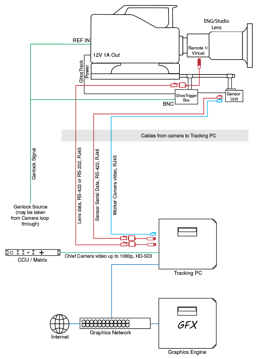
4 Setup
The setup of the tracking system itself is the same as with Pixotope Vision. The only exception is that the sensor camera has to be synchronized to the tracking pattern slice of the LED panels. It can still recognize markerless features and infrared stickers additionally in case they are needed to add feature points outside of the LED wall.
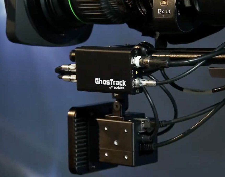
4.1 Hardware Setup
Two power cables connect the Trigger Box to the sensor camera and optionally to the infrared ring light. Multiple 4-pin XLR adapters can supply the Trigger box with power from the film camera.
4.2 Software Setup
For the operating system and Pixotope Vision installation, please follow the respective manual.
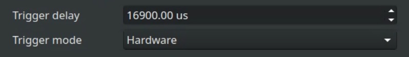
To set up the GhosTrack Trigger Box, navigate to the Camera tab in the Worker Settings and activate Show Expert Settings:
-
Select the Trigger mode to be Hardware
-
The Trigger delay can now be used to synchronize the sensor camera with the LED wall
-
As soon as the GhostFrame LED panels is set up with the tracking pattern slice, continue with chapter 5 below
4.3 GhostFrame Setup
The final setup for the GhosTrack has to be done in accordance with the respective personnel from the GhostFrame technology operating the HELIOS Processing Platform from the vendor MVR. The goal is to optimize the division of the frames into slices for the different contents.
The optimum is to have the longest possible display time for the video content and the shortest possible display time for the tracking pattern. The shorter the display time for the tracking pattern is, the smaller the saturation loss in the video content for the human eye gets. In addition, the brightness value for the marker slices might be reduced to make the visibility even lower. However, a shorter display time and darker brightness for the tracking pattern reduces the visibility of the tracking pattern for the sensor camera.
Keep in mind that the film camera when synchronized properly always sees its video content without any quality loss.
5 Operation
The Trigger delay delays the full exposure time of the sensor camera. The goal is to have the exposure time of the sensor camera starting at the beginning of the tracking pattern slice and ending at the end of that same slice.
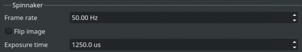
Let’s say a production is shot at 50 frames per second and the content is divided into 16 slices per frame. This results in one frame lasting 20ms and one slice lasting 1,25ms. One slice is then the shortest time that a tracking pattern can be shown and consequentially 1250us is the maximum possible exposure time of the sensor camera. Keep in mind that the exposure time determines the brightness of the pattern for the sensor camera.
Since the tracking pattern has to be shown again for the same amount of time but inverted, this results in 14 slices or 17,5ms being left for video content.
-
Set the sensor cameras' Exposure time to either the maximum possible value or a value that makes the pattern sufficiently visible
-
Increase the Trigger delay until the tracking pattern is visible with full quality
-
You might need to increase the gain at the sensor camera in order to allow the LED pattern to be displayed darker