Configure routing
Set up camera input switching
This features is available when using an XR license
You can switch the active camera system (video and tracking source) between the camera systems defined in Group A and Group B.
Enable camera input switching
Enable “Camera input switching" in SETUP > Show > Show settings
Define camera system groups
Per machine: Route the 2 camera systems which should be switched between
Select the first camera systems to be in Group A
Select the second camera systems to be in Group B
Switch between the groups
Switch using the Group A/Group B radio button
OR set up a toggle in the Control panel switching the
ActiveCamerasGroupin the Store state between0and1.
Create widget
Press
Tin your control panel to bring up the Widgets toolboxSelect a tab widget
Click and drag on the canvas to place it
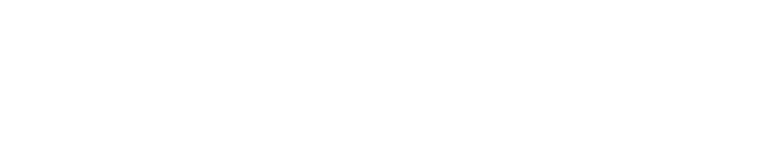
Change the Display Name on the tabs via Widget tab > Options
The values can be disregarded as we don’t need them
Listen to the Director action
Make sure that you have routed your cameras and defined the camera system groups before you listen to the action. For every change to on of the groups, the actions need to be updated!
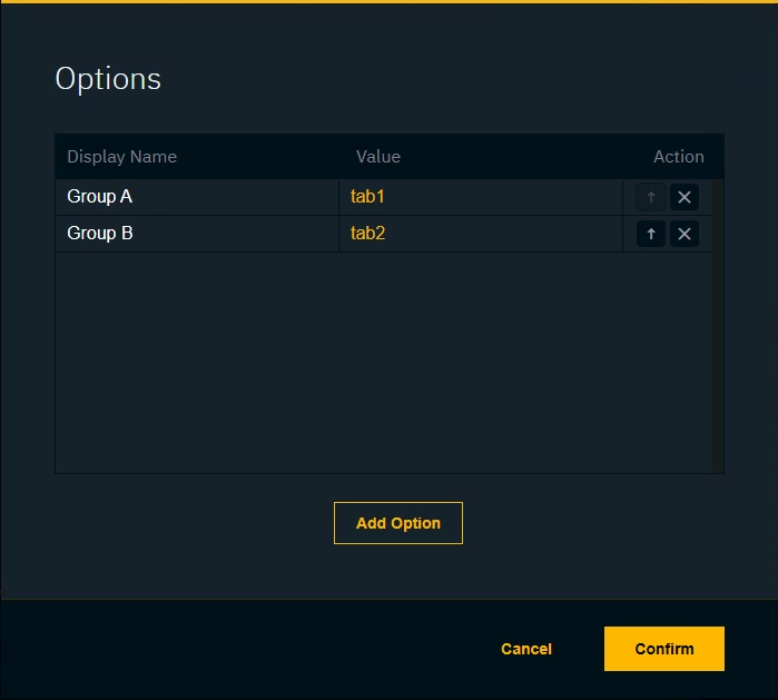
Select the API Log tab
Listen to the Call type by enabling the
CallfilterClick the
xicon to clear the logsClick
Playicon to start listening to messages
In Director: Switch from Group A to Group B and back again
Click on the
Pauseicon to stop listening to messages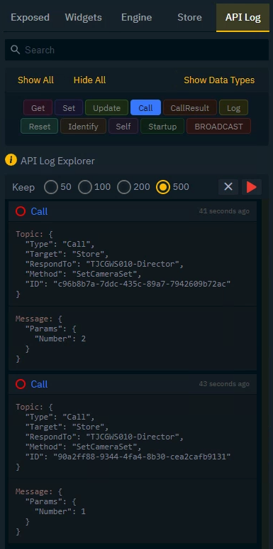
Link action
Select the
TAB 1 CLICKaction of the tabs widget in the Actions List
Drag the second Set message (Switching to Group A) onto the Source/Target of this action
Click on the
Triggericon to turn this action from Read to Send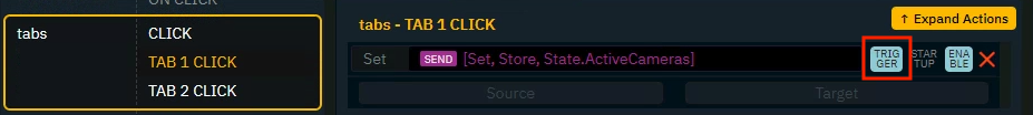
Repeat these steps for the
TAB 2 CLICKaction and the first Set message (Switching to Group B)Press
Ror the "Play" button in the header to try it out
If multiple camera systems are routed to one machine and none of them are part of any group, the first camera system is used.
Set up input and output routing
On SETUP > Configure > Routing > Camera, Media and Object routing we set the input routing for:
Camera systems
Object trackers
Media inputs
and the output routing for:
Media outputs
For SDI signals (AJA and BMD) this means recreating the physical routing.
Set up input routing
Set the Genlock source for each machine:
Genlock is used to synchronize the camera and tracking data to provide guaranteed video output timing
External ref - Genlock comes from an analog external ref signal. Both Blackburst and Tri-level syncs are supported
External SDI(n) - Genlock is derived from a specified SDI input’s video clock
Freerun - an internal Genlock is generated - this does not guarantee synchronisation with other machines.
There should be one common source for the Genlock signal
Add all camera systems and media inputs to the respective machines
Optionally enable Body Pose Estimation - Learn more about how to Set up Body Pose Estimation (BPE)
Set their Input sources
For AJA and BMD: Select the input spigot
For NDI: Select the input stream
Add all object trackers whose tracking should be available on a specific machine
Only one camera system can be added per machine.
Set up output routing
Add outputs for each machine
Set their output destinations
For AJA and BMD: Select the output spigot
For NDI: Name the output stream
This features is available when using an XR license
In Director
Route 2 or more media outputs to the machine
In case one of the channels is a key, choose "Key" in VideoI/O > Video output > Output type
In Editor
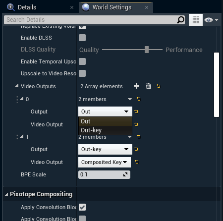
Add 2 output channels by clicking the + icon on World Settings > Pixotope World > Video Outputs
Under “Video Output” choose the channels you want to output
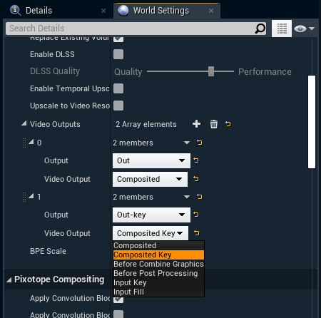
Choose to which "Output" this channel should be mapped
The frame rate of inputs and outputs must be the same!
For example, if your production needs to output in 50p, choose a 50p output format and set your physical camera and the camera system in SETUP > Configure > Video I/O up to match.
Review incoming tracking data routing
The incoming tracking data routing is done on the individual camera systems and object tracker groups. On SETUP > Configure > Routing > Incoming tracking data routing you can then review it.
Review the assigned tracking services
For camera systems: Use the tracking service the camera system will be routed to
For object tracker groups: Use the tracking service most of the object trackers will be routed to
Check the IP addresses and port number of the assigned tracking services on your camera and object tracking system
Send the tracking data to one of the listed network adapters and its specified port
For the Ncam system, the IP address and port number should be entered in the Advanced section of the camera tracking protocol
Check the status field
Your tracking configuration is set up correctly if it shows incoming data
You can also show logs or check the Network status in the Editor