Configure camera input switching
Learn more about how to Configure camera input switching
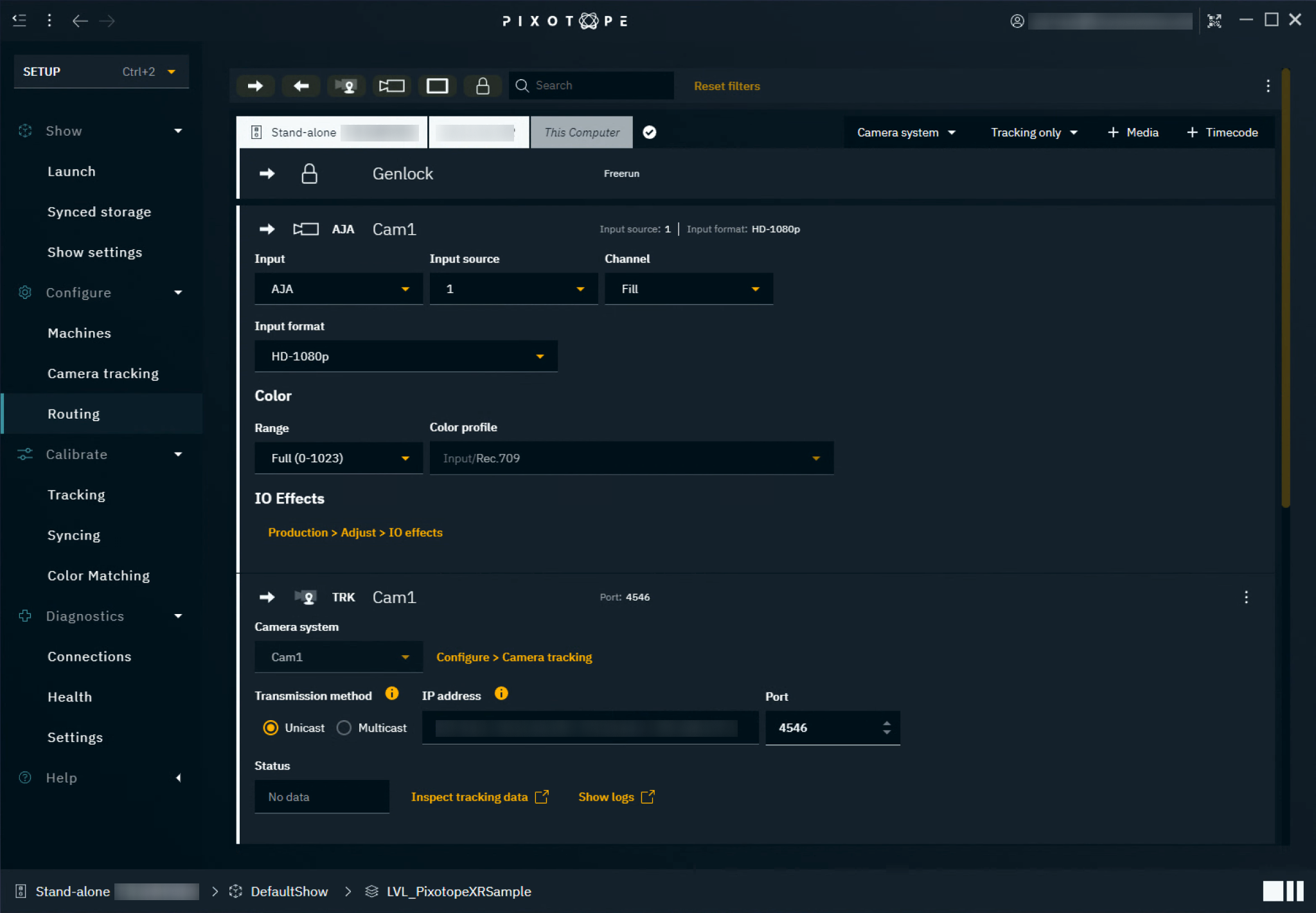
Set up routing
On SETUP > Configure > Routing > Camera systems and Media inputs and outputs are routed. For SDI signals (AJA and BMD) this means recreating the physical routing.
Update the default settings of your show before you start routing.
Set up Genlock
-
Set the Genlock source:
-
Genlock is used to synchronize the camera and tracking data to provide guaranteed video output timing
-
External ref - Genlock comes from an analog external ref signal. Both Blackburst and Tri-level syncs are supported
-
External SDI(n) - Genlock is derived from a specified SDI input’s video clock
-
Freerun - an internal Genlock is generated - this does not guarantee synchronisation with other machines.
-
-
There should be one common source for the Genlock signal
-
Route your tracking source
Add a camera system
-
In the right corner of a machine click on "Camera system" and choose the camera system to route
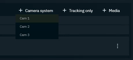
-
A combined media and tracking input gets added
Unless camera input switching is enabled, only one camera system can be used per machine.
Update media input settings
-
Change the Input type if needed
-
Change the default in SETUP > Show settings
-
-
Set the input source and adjust their settings
-
See Supported input and output types for options
-
-
Optionally: Adjust the input format and color profile
Input channel
|
Fill |
default setting, allows for using the internal video keyer (default) |
|
Key - External Key |
the video is keyed externally and is provided as a separate fill and key signal |
|
Fill/Key - External Key |
the video is keyed externally and is provided as a combined fill and key signal Don’t forget to select the corresponding fill! |
Learn more about Supported input and output types
Learn more about color profile and color space in how to Configure your color pipeline
The frame rate of inputs and outputs must be the same!
Changing it individually can lead to unexpected results.
Update tracking input settings
-
Choose the transmission method
Unicast
Send data from a single tracking source to a single tracking service.
Recommended if you have a single tracking source per tracking service OR if your tracking system can send reliably to multiple IP addresses.
-
The IP address field shows all network adapters of the machine the tracking service is running on.
-
Note down the IP address of your preferred network adapter
NOTE: We recommend using a different network adapter for tracking to the one specified in Machine settings, which is used for Pixotope communications.
-
-
Change the UDP Port if needed
-
This is the UDP port that tracking data is received on. Note it down.
-
-
On your camera tracking system:
-
Set the destination IP address and UDP port number to the values noted down
-
Multicast
Send data from a single source to a group of interested tracking services in a single transmission.
Recommended if your tracking system does not allow sending to multiple IP addresses.
Most current IP stacks support the IP multicast routing protocol. Check the manual of your network hardware for details.
-
Note down the suggested default multicast IP address or change it if needed
-
Available range: 224.0.0.0 - 239.255.255.255
-
-
Change the port if needed
-
This is the UDP port that tracking data is received on.
-
-
Choose your preferred network adapter which should handle the multicast data
-
NOTE: We recommend using a different network adapter for tracking to the one specified in Machine settings, which is used for Pixotope communications.
-
-
For any additional camera system which should use the same tracking data
-
Choose the same multicast IP address and port as well as the preferred network adapter of the tracking service
-
-
On your camera tracking system:
-
Enter the noted down multicast IP address and UDP port number
-
For the Ncam protocol
Enter the Ncam’s server IP address - the port number cannot be changed.
Check tracking data status
-
Check the status field
-
xx Hz(incoming tracking data frequency)-
The setup was successful
-
-
Other
-
No incoming tracking data detected. Check your setup.
-
-
Alternatively you can also
-
Inspect tracking data via the Tracking plotter
-
Show logs of the tracking service
-
in the Editor: check the Network status
Route additional media inputs
Add additional media inputs, if you need untracked video sources in your level (for example, the input for a virtual monitor).
-
Click Add > Media > Input
-
Name your input
-
Change the Input if needed
-
Change the default in SETUP > Show settings
-
-
Set the input source and adjust their settings
-
See Supported input and output types for options
-
-
Optionally: Adjust the input format and color profile
Learn more about how to Add a virtual monitor or other video feeds
Route output
-
Click Add > Media > Output
-
Name your output
-
Change the Output if needed
-
Change the default in SETUP > Show settings
-
-
Set the output destination and adjust their settings
-
See Supported input and output types for options
-
-
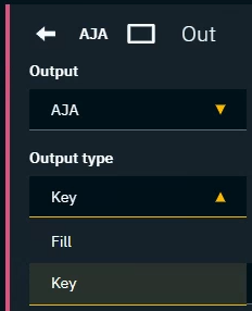
Optionally: Adjust the output type
-
Optionally: Adjust the output format and color profile
Output type
|
Fill |
for internal compositing mode (default) |
|
Key |
for external compositing mode |
Learn more about Compositing modes
The frame rate of inputs and outputs must be the same!
For example, if your production needs to output in 50p, choose a 50p output format and set your physical camera and the camera system up to match.
Route more than one output per machine
This features is available when using an XR multi-wall license
In Director
-
Route 2 or more media outputs to the machine
-
In case one of the channels is a key, choose "Key" in Output type
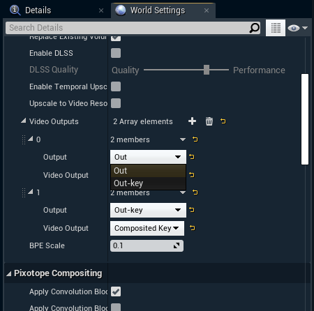
In Editor
-
Add 2 output channels by clicking the + icon on World Settings > Pixotope World > Video Outputs
-
Under “Video Output” choose the channels you want to output
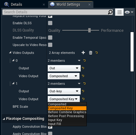
-
Choose to which "Output" this channel should be mapped
Filter on machines or types
Use the filter and search bar on the top to focus on
-
Specific machines
-
Inputs or Outputs
-
Types
