The Pixotope Event System provides a robust event-handling framework.
It allows a quick setup for the triggering of Unreal blueprints and animations to achieve whatever effect is desired, creating repeatable, deterministic actions. This works by means of firing off actions called on a list of cues.
It supports direct, remote, or pre-programmed timecode-driven operation, with all action/cue organization and event handling, driven through an intuitive and flexible master blueprint.
Early versions of the Pixotope Event System have been used in high-profile productions like Super Bowl, Eurovision, League of Legends World Championship, and others.
Academy Tutorial - Pixotope Event System
-
Learn how to set up the Pixotope Event System
Preparation
Add the Pixotope Event System content to your project
Using the Pixotope Event System in a project will inherently alter the imported assets. As a result, you should always use a fresh copy of the content for every new project.
-
Click on “Add/Import” in the Content Browser
-
Select “Pixotope Event System” from Pixotope > Add Pixotope Content
The content is copied into your project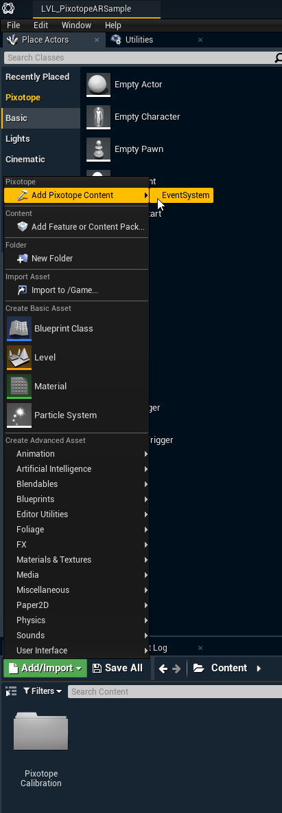
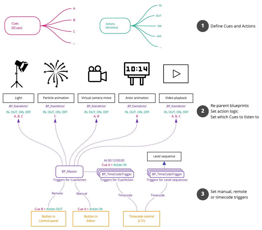
Define Cues and Actions
Cues represent distinct segments of a production on which actions are executed. Blueprints and level sequences can then be set up to listen to specific Cues and run their triggered Action logic.
The Event System allows you to define any number of cues and allows you to extend the included default actions.
Example
Our production has a fireworks segment. For this, we define a Cue called "Fireworks". The blueprint handling the particle animation needs to be set up to react to all default Actions and listen to the "Fireworks".
-
On the IN-Action it starts slow, ramping-up the fireworks display
-
The OUT-Action ends the fireworks with a final blast
-
The ON and OFF-Actions are set up as fail-safes and for testing/debugging where the particles immediately jump to a full ON/OFF state
Define Cues
Cues are stored in the ECues enumerator.
-
Open the ECues enumerator
-
Edit the display name and description based on your production segments
-
Add more items if needed
Define additional Actions
Actions are stored in the EAction enumerator. The Pixotope Event System comes with the following default actions.
Default actions
-
IN - Trigger an IN-transition and end in the ON state
-
OUT - Trigger an OUT-transition and end in the OFF state
-
ON - Go instantly to the ON state
-
OFF - Go instantly to the OFF state
The default actions cover most use cases. However, should the project require more actions do the following:
-
Open the EActions enumerator list
-
Add more Actions
Note: Every action needs a corresponding function in the BP_EventActor.-
Open the BP_EventActor
-
Duplicate one of the functions of the default actions
-
Update the name of the new function to the one of the action
-
Prepare blueprints
In order for the Event System to index your blueprints, they will first need to be reparented to the BP_EventActor.
Reparent blueprints
-
Open the blueprints which should be triggered by the event system
-
Click on "Reparent blueprint" in the File menu
-
Select the "BP_EventActor"
Set Cues to listen to
Specify which Cues each blueprint should listen to.
-
Go to the "Details" panel in your blueprint
-
Assign one or multiple Cues this blueprint should listen to
or on a per-instance basis, directly in our scene
Add blueprint logic
With BP_EventActor assigned as the parent, we can now add the inherited Action events, and wire them into the desired blueprint logic.
It is good practice to ensure that calling any of the available Actions, at any time, results in replicable and correct behavior.
-
Add all Actions to the blueprint
-
Add the desired blueprint logic to it
-
Optionally use a "Switch on ECues" node to execute different Action logic depending on the sent Cue
Set triggers
Once all our Action logic has been wired up and Cues are assigned, we are ready to set up triggers.
Add BP_Master to the level
BP_Master is the beating heart of the event system. It is responsible for rounding up all actors that belong to the system and ensure that actions are called correctly on them.
-
Drag BP_Master into the level
Use manual/remote event triggers
-
Open the BP_Master blueprint
-
Add a Custom Event and give it a distinct name
-
Connect a Cue Action and select which Cue Action should be triggered
-
Repeat these steps for all events which need to be triggered
-
Save BP_Master
Set up manual event triggers
For every Cue Action, a debug button on BP_Master is added.
This can be disabled by unchecking "Call in Editor" on the Details panel of the Cue Action.
Set up remote event triggers
With the Custom Events set up in BP_Master, they can be triggered using the Control Panel.
-
In Director, open an existing or create a new control panel
-
Add a trigger widget
-
As a target and select one of the created events on BP_Master
Learn more about Creating a custom control panel
Test the event triggers
-
Enter Play or LIVE mode
-
Trigger the events using the debug buttons or the control panel
Use timecode triggers
The Pixotope Event System also supports automatic triggering with timecode (LTC).
Set up timecode (LTC)
Linear Timecode (LTC) is a clock stream that can be supplied in a number of ways. We can use it to facilitate the automated execution of Cue Actions.
We receive an LTC signal through the video card, either
-
as analog audio on a breakout cable OR
-
via an SDI input
Learn more about how to setup LTC for AJA video cards
Linear Timecode (LTC) is a clock stream that can be supplied in a number of ways. It is typically used for synchronization in video production, filmmaking, and live events.
We can use it to facilitate automated execution of Cue Actions, through the Pixotope Event System. If we feed multiple engines the same Timecode signal, they will all trigger at the same time - imperative when frame-perfect accuracy is required, for instance for hitting lip sync or matching audio cues!
LTC can also be used to synchronise video and tracking together, or when recording incoming tracking data.
We receive an LTC signal through the video card, either:
-
via an LTC port (as analog audio on a breakout cable) OR
-
via an SDI input (embedded into the video signal)
In a production environment, this signal would usually come from audio, especially if events had to be triggered on audio playback cues. However, we can easily set up a test environment where we generate and handle our own timecode.
Supported methods
Setup Analog audio timecode
Setup for AJA video cards
AJA Kona 4 and 5
For the Kona 4 and Kona 5 cards, analog audio timecode can be received on the “LTC In” cable on the multifunction breakout cable.
The state of the Timecode can be seen on the AJA ControlPanel, by viewing the Timecode tab and selecting the source as “LTC Port”. if timecode is received, it is displayed in the control panel.*
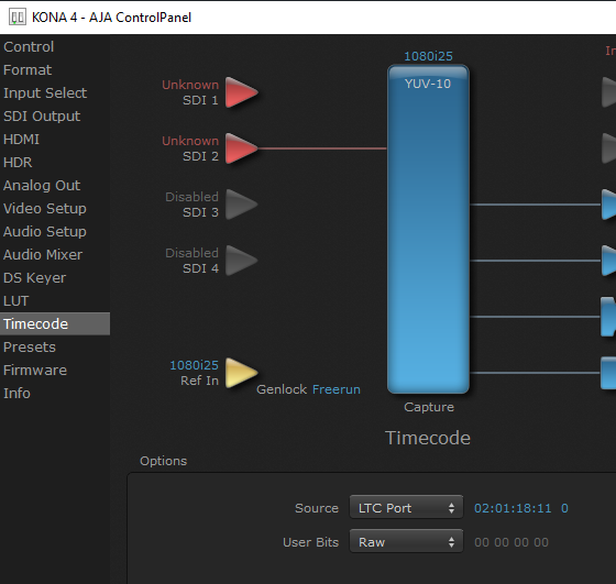
*Note the timecode display does not update in real-time, but refreshes every second.
AJA CORVID
For the CORVID video cards there is a joint Genlock/LTC In analog connector.
Pixotope does not genlock to Timecode and always requires a genlock reference as analog black/burst or tri-level, or to genlock from an SDI input reference signal.
We suggest for the Corvid cards it is easier to genlock to an SDI input and to reserve the “genlock/LTC In” input for LTC.
N.B. It is possible to construct an auxiliary LTC input cable that connects to header pins on the Corvid series of cards if you need to use both analog genlock and analog LTC concurrently.
Testing LTC Input
It is very simple to set up an LTC source. You need:
-
Windows computer with a headphone audio output
-
Source audio file
-
Program to playback the file
-
An audio cable from a 3.5mm plug to a BNC connector
We suggest you plug in your headphones to the audio output to verify the signal. Test first that you can hear Windows alert sounds. You may need to adjust the Windows audio mixer controls.
-
Create or download an audio LTC file
-
This should be in .wav format and at 44.1kHz. For ease of testing, we have supplied some working test files here: https://drive.google.com/file/d/1JqEY30n9tOAOMLDz6dN7Exp7XGByLIdr/view?usp=sharing
-
Alternatively, you can create your own file at this site: http://elteesee.pehrhovey.net/ltc/create
-
An LTC file has to be created in the same time base that your video is using - so for 25 or 50Hz video rates, choose a timecode base of 25; for 29.97 or 59.94Hz video rates, choose a timecode base of 29.97
-
-
Select a program to playback the file
-
Windows Media Player is sufficient. You could also use Audacity: https://www.audacityteam.org/download/
-
Play one of these LTC files back through the headphones - the sound should “warble” quite loudly - timecode has a very distinctive sound
-
-
Connect the audio cable
-
Connect the audio cable from the headphone output jack to the “LTC In” connector of your AJA card
-
-
Open the AJA ControlPanel
-
Select the Timecode tab and set the source to “LTC Port”
-
Ensure that the Capture block is showing the correct timebase, and change it if necessary
-
-
-
Play the file
-
Play the LTC file again and check that the timecode display is showing the correct value in the AJA ControlPanel
-
If the correct timecode can be shown in the AJA ControlPanel, Pixotope will be able to access the LTC values.
Windows Media Player can run the LTC .wav file by just right-clicking on the .wav file. If you want more control or to adjust or trim the signal, then we suggest using Audacity.
Troubleshooting LTC Audio
Run the LTC input:
-
If the timecode isn’t shown in Pixotope, check that the timecode is shown in the AJA ControlPanel
-
If it is not shown in the AJA ControlPanel, check that “LTC Port” is selected and that the sync rate of the Capture block matches the LTC file rate
-
If it still doesn’t work, check the audio output of the source computer on headphones. Is it warbling like timecode? Is it loud?
-
If it sounds incorrect, or you have no sound, check the Windows Audio Mixer options or try a different LTC file
-
If it doesn’t appear to playback in Audacity, check with Windows Media Player
Connecting Audio LTC to Multiple Pixotope Engines
The AJA Kona 4 and Kona 5 cards have an “LTC In” and an “LTC Out” cable, so that Audio LTC could be looped through one machine to the next in a “daisy-chained” configuration.
This is not the best way, however, because any break in that chain could stop the downstream machines from receiving the LTC signal.
A better approach is to distribute the LTC signal through an audio distribution amplifier (d/a), and provide a separate cable from the d/a to each of the “LTC In” ports of the AJA cards.
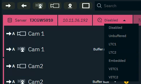
Using timecode in Director
-
Go to SETUP > Calibrate > Syncing
-
For every machine, choose your primary timecode source
-
Launch a level
-
Check if the engine receives timecode by clicking on the timecode source icon

-
For AJA, you can also verify that timecode is received, by viewing the Timecode tab of the AJA ControlPanel
-
Embedded LTC: set source to “RP188 LTC” or “RP188 VITC”
-
LTC Port: set source to “LTC Port”
-
-
-
If needed add a secondary timecode source
Only one Embedded source is possible at any time.
A level needs to be running as the timecode is reported by the engine.
Using timecode in Editor
-
Access the timecode using the "Get Video IO Timecode" blueprint node
-
the index refers to primary or secondary within Director
-
Outputting timecode via SDI
Timecode is embedded in all SDI outputs.
Set up timecode event triggers
For this, we utilize the BP_TimeCodeTrigger actor which is also used if we wish to trigger Level Sequences directly.
For Cue Action events on blueprints
BP_TimeCodeTrigger acts as a trigger source and sends a Cue Action call to BP_Master. This then gives the exact same result as if the Cue Action was triggered manually.
-
Drag a BP_TimeCodeTrigger into your scene
-
Check "Run Event" and set which Cue Action it should trigger
-
Set the timecode at which the Cue Action should be triggered
-
Check the "Live" checkbox to enable the trigger
For level sequences
-
Drag a BP_TimeCodeTrigger into your scene
-
Select the Level Sequence which should be triggered and leave "Run Event" unchecked
-
Choose whether the sequence should be looped
-
Set start and stop timing overrides, letting you “slip” the level sequence without having to edit the actual sequence asset
-
-
Set the timecode at which the Cue Action should be triggered
-
Check the "Live" checkbox to enable the trigger
More options
Timecode
Most shows tend to start each segment at an arbitrary start time, usually a whole hour, so remember to offset your start time by that value.
Make sure the timecode’s FPS (LTC) is set to the actual frame rate of the production - a timecode trigger set to happen at frame 50, will never be executed if the inbound timecode is at 25 frames per second!
“Display Timecode” simply plays a text element directly above the blueprint, showing the current TC. Excellent for debugging and checking timings.
Live
By default, all BP_TimeCodeTriggers are set to “Standby”. This means that they will not trigger if their timecode Cue is hit. This is useful in a live production environment, where we do not wish to accidentally have graphics brought up too early due to, for instance, an audio check. “Live” makes the trigger start listening to timecode, and will make it execute once the trigger timing is hit.
Mock Timecode
If you are working on the event cues, and do not have access to live timecode, we have a handy alternative in Mock Timecode. This is not an actual live signal, but rather a clock that starts ticking from a predefined starting point fired off manually or at beginPlay.
Useful for testing individual Cues without needing an external trigger source. Can be enabled or disabled through BP_Master, and made to default to active or idle on BeginPlay.
Debug buttons
The debug buttons/events can be used to set live/standby state, start/stop mock timecode, and force a trigger.
For setting project-wide live/standby, or doing other wide calls, please use the relevant events in BP_Master.
Debug timecode triggers
BP_TimeCodeDebug allows you to print timecode to the log, as well as on-screen, and is primarily used to ensure that timecode is actually running when you go live in a production.
We recommend having one of these in your scene. It will need to be connected to a TimeCodeTrigger actor to function correctly, and will display color-coded TC on-screen if “Print TC” is enabled, and live/mock timecode is being received.
-
Green - Level Sequence playing
-
Cyan - Standby mode
-
Red - Orange - Live, waiting on a trigger