Any change of position or orientation as well as zoom, focus or aperture of the TalenTrack cameras makes a new calibration necessary!
Make sure you have saved the settings in the Client window during the setup. Otherwise the videos will not appear in the calibration window.
1 Distortion and Offset
-
Start the TalenTrack Calibration
-
Place the board in the tracking area
The Detection tab includes further settings regarding the pattern detection. However, these are advanced settings where the default values should work fine. Creating a good overall brightness inside the studio or with the camera settings should be the first approach. If the software still struggles to recognize the pattern, change Detector Output to binary and try adjusting the Segmentation threshold.
-
Click Start Autosampling
-
Start moving the calibration board while trying to keep it detected in as many cameras as possible. The software will take Samples automatically when the board is in a new position, indicated by a green frame appearing around the videos
-
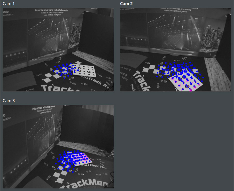
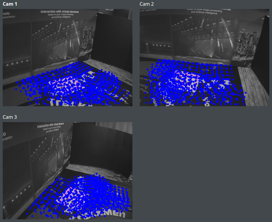
Control the Samples taken, indicated by blue dots. The following requirements should be met:
-
The area covered with dots should be at least 25% of the image
-
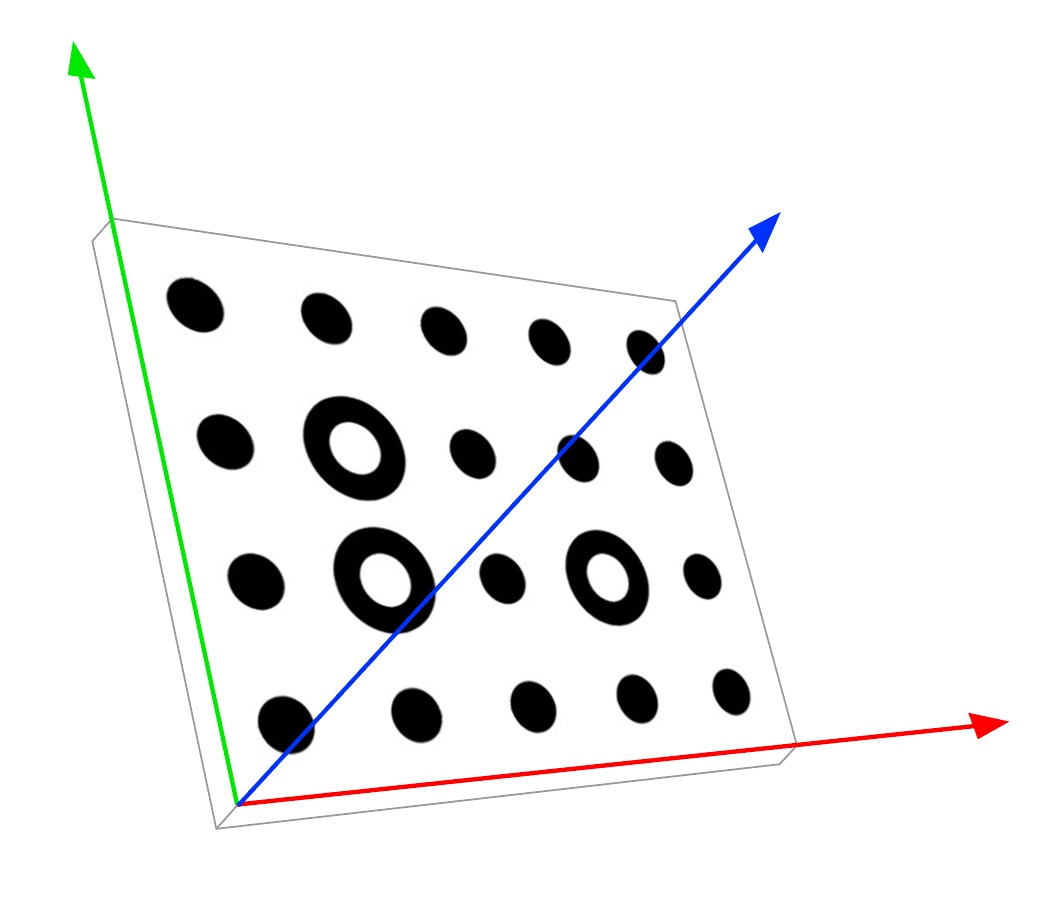
Dots should cover the area between the center of the image and at least one of the corners of the image (see Illustration 3)
-
-
Click Stop Autosampling
-
Click Run Calibration
-
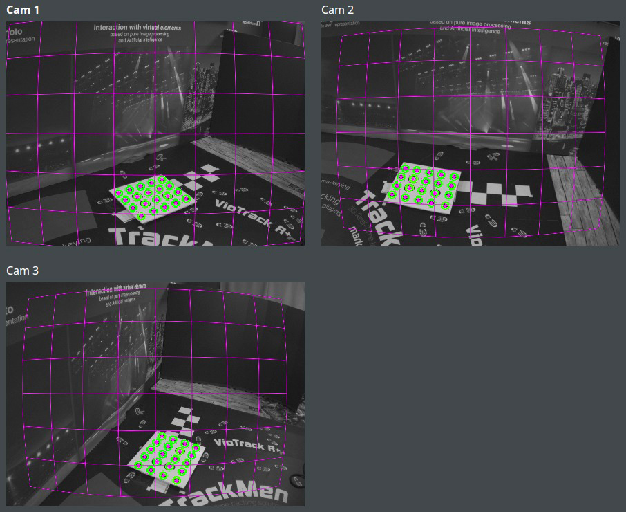
After the calibration is finished deactivate Visualize Samples and activate Visualize Distortion
-
Control the Distortion grids that are shown in the videos:
-
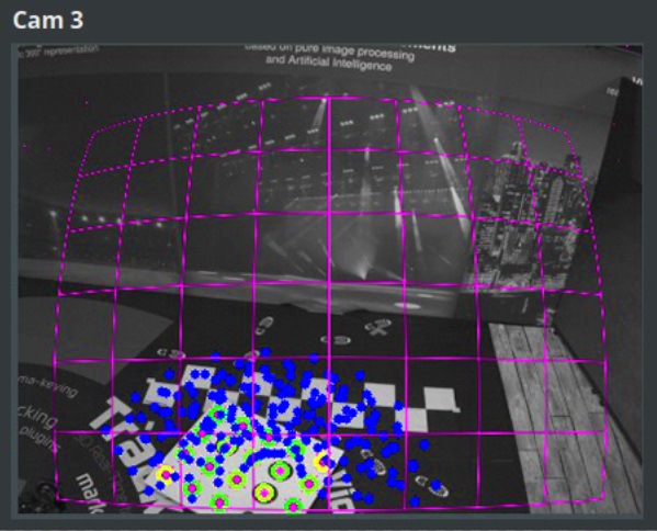
The grids should appear centered in the image and not like Illustration 5
-
The distortion should seem realistic in relation to the focal length of the length of the lens. A wider focal length causes a stronger distortion
-
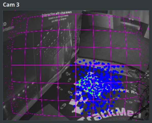
The grids should not dissolve as visible in Illustration 6 in the grids corners
-
All circles on the calibration board should appear green
-
-
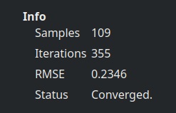
Control the Info section on the left side
-
The number of Iterations is depended of the amount of Samples taken. It must be below 500
-
The RMSE is an average calculation error. It should be below 0.5
-
Status should say Converged
-
-
If the distortion grid of one camera is unsatisfying, try lifting the calibration board up and taking some more samples with the board closer to that camera and running the calibration again
-
If unsatisfied with the result, you can also click Clear Samples and try the process from the beginning, but covering more area of the videos
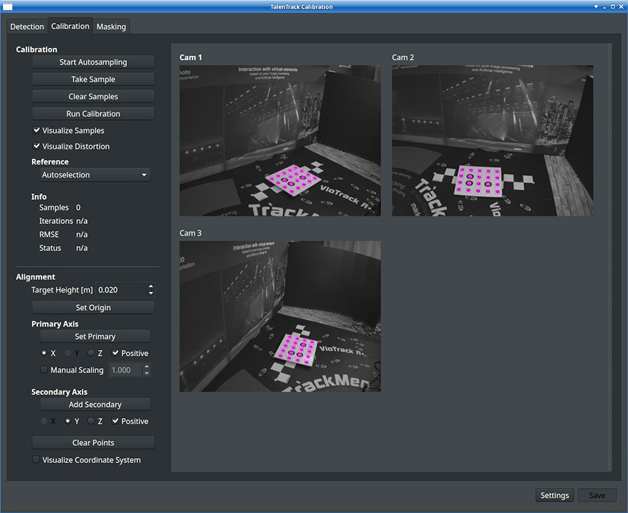
2 Coordinate System
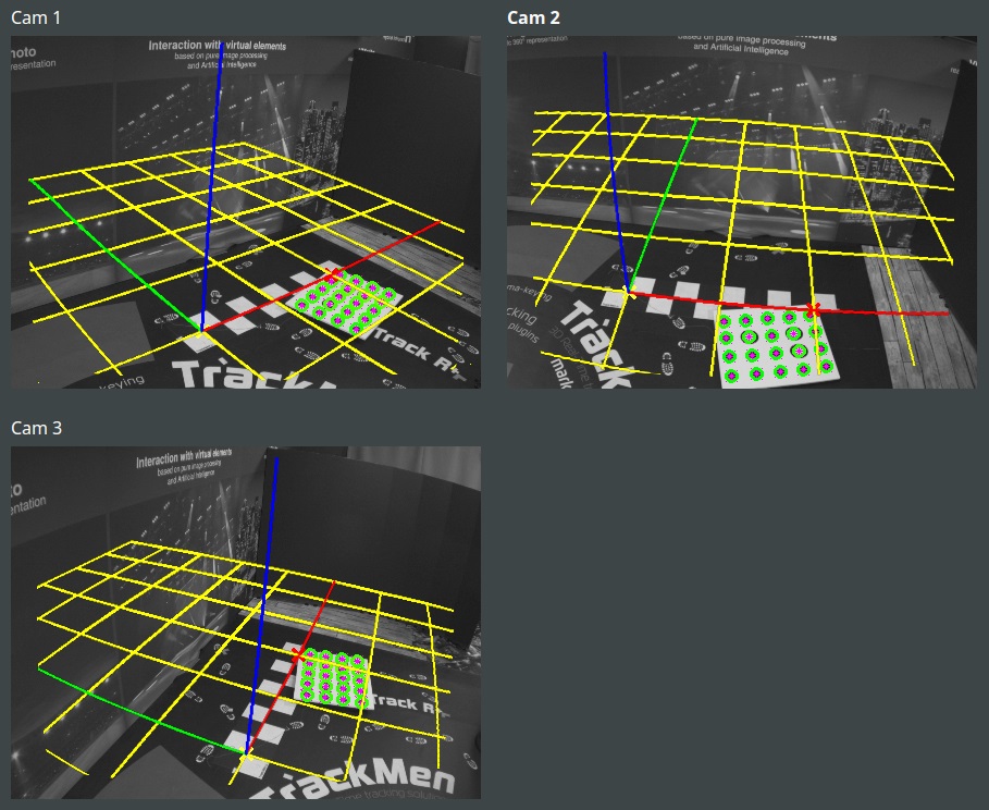
Three points must be defined in the studio to create the 3D coordinate system. Ideally the zero plane is the floor. The TalenTrack coordinate system should match the one from the camera tracking system used.
The three points (Origin, Primary, Secondary) are set with the calibration board. They are set while the board is recognized in the images in the calibration window.
-
when Set Origin is clicked, the three points to define the coordinate system are taken from the corners of the calibration board. The lower left one will be the origin, the lower right one the primary axis and the upper left one the secondary axis. The tertiary axis results according to the “right-hand-system” (see 4.2 Worker manual). With this function the entire coordinate system including the scale can be set with one click. It only requires the calibration board to be placed and oriented correctly
-
when clicking Set Primary or Add Secondary, these points will be set wherever the lower left corner of the board is at that moment and replace the respective points taken when the origin was taken. The advantages of setting Primary and Secondary points like this are:
-
greater distances between the points can be achieved, meaning higher precision
-
multiple Secondary points can be added, meaning higher precision
-
negative directions of the axes can be used for defining the orientation
-
-
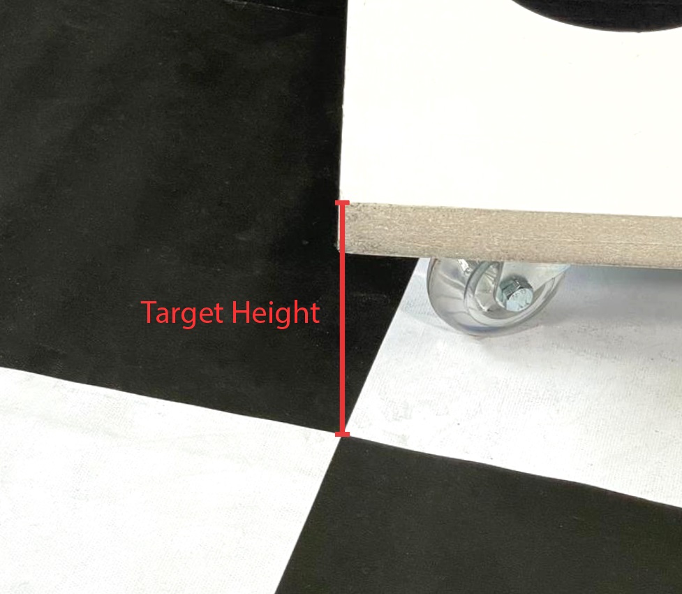
Target Height offsets the points along the tertiary (blue) axis. The board is 2cm thick, so the default value of 0.02m will set the points at the rear corner of the board. For example if the board lies flat on the ground a value of 0.02m will set the origin onto the floor
-
The scale will be set automatically with the board when clicking Set Origin. It can be set manually with Manual Scaling after setting the primary axis point. The value then represents the distance between the origin and the primary axis point
With a greater distance between the points, a higher precision can be achieved for the coordinate system!
-
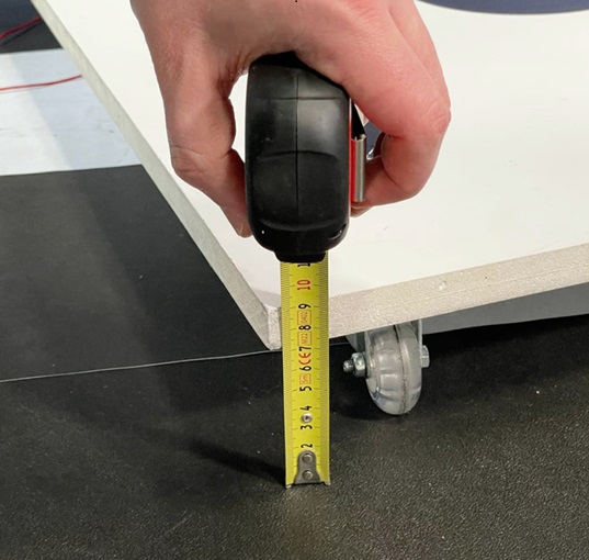
Measure the calibration boards height from the ground. In our example the calibration board has wheels underneath to be moved around more easily in the studio
-
Type the value into the Target Height field
-
Place the lower left corner of the board above the desired studio origin and click Set Origin
-
Activate Visualize Coordinate System

-
Control the grids position
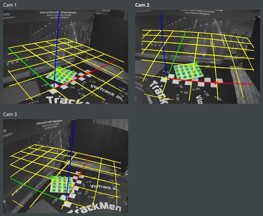
To increase the precision, we will set all three points in this example.
-
Place the lower left corner of the board over the desired primary axis point and click Set Primary
-
Control the grids updated position
-
Place the lower left corner of the board over a secondary axis point and click Add Secondary. The secondary axis point should be as far away from the primary axis as possible
-
Control the grids updated position
-
Optionally: add more secondary axis points to potentially increase the precision
-
Optionally: set the Manual Scaling with the measured distance between origin and primary axis point
-
Click Save
The calibration is saved in the folder /home/tracking/pxTalenTrack/calibration/. If you want to backup a calibration, duplicate this folder and rename it.
-
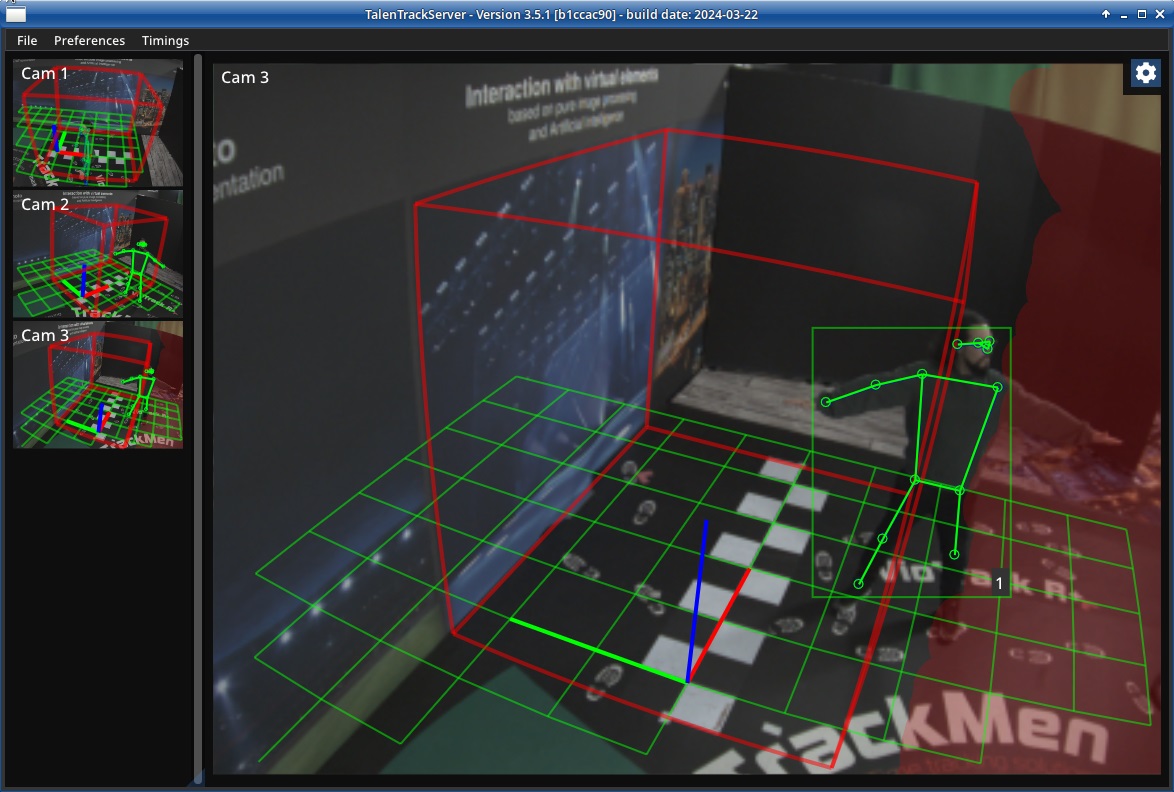
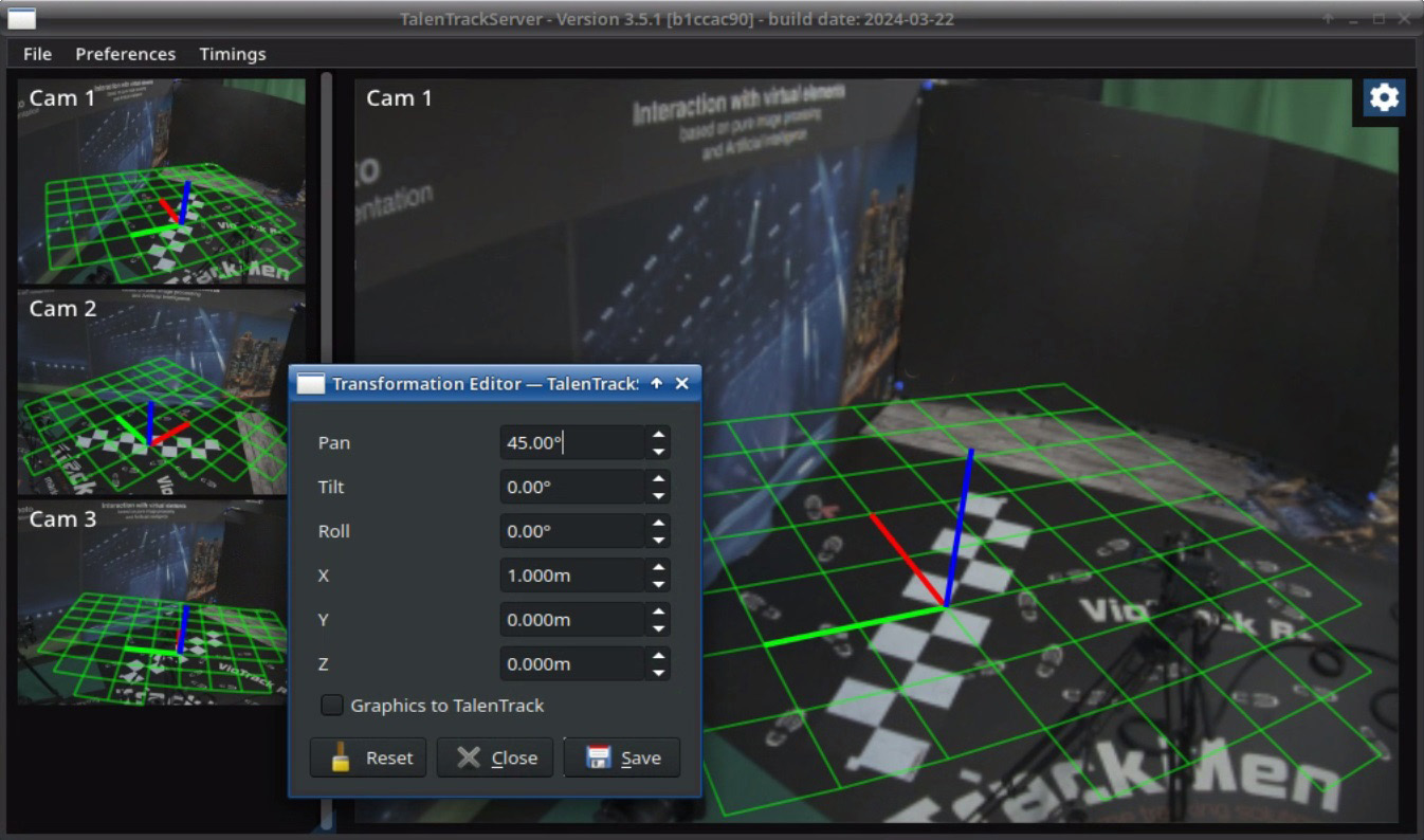
Optionally: the orientation and position of the coordinate system can later be modified in the TalenTrack Server window under Preferences and Transformation
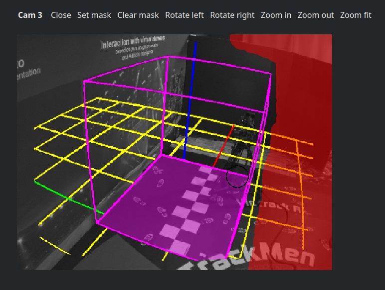
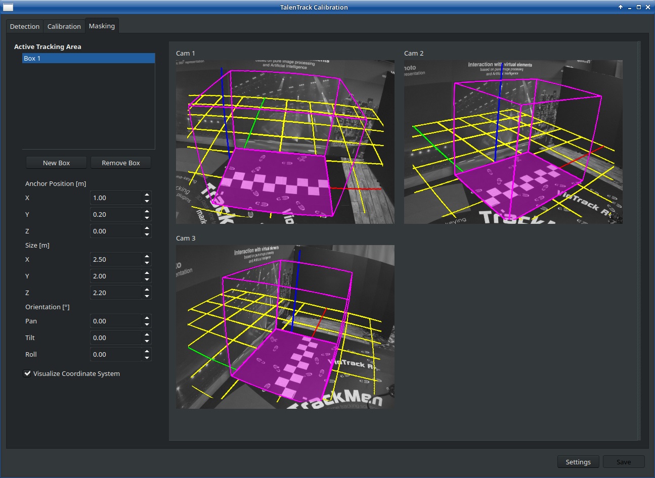
3 Masks
Masks enable the user to define exactly in what area tracking and image analysis takes place. This is optional but can be useful in case any of the TalenTrack cameras is pointing in a direction where persons are that are not supposed to be tracked, like operators.
There are two methods of masking:
-
Volumetric masks define the 3D space in the studio in which a recognized person is given an ID and tracked with 3D data. Persons standing in the camera view but outside the volumetric mask are still detected but no 3D data is calculated
-
2D masks define the part of the TalenTrack cameras frames where image analysis is applied. A person standing in the field of view of the camera but in a masked out part of the image will not be detected
3.1 3D Masks
-
Go to the Masking tab in the Calibration window
-
Click on New Box to create a new volumetric mask
-
Define the Size of the mask and move it with Anchor Position in the right position in relation to the studio origin
-
Angles of the mask can be adjusted with Orientation
If a corner point of the mask lies behind the camera, the mask will not be displayed in the video.
3.2 2D Masks
-
Double-click on a video in the Calibration window in the Masking tab
-
Use the courser as a brush to mask out parts of the area with the left mouse button. Masked out areas are colored in red
-
The right mouse button removes the mask in the same way
-
When finished click on Set mask