1 Preface
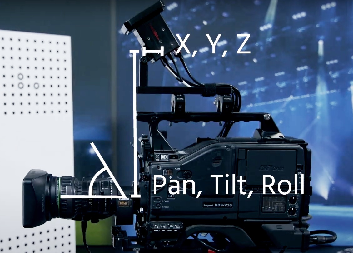
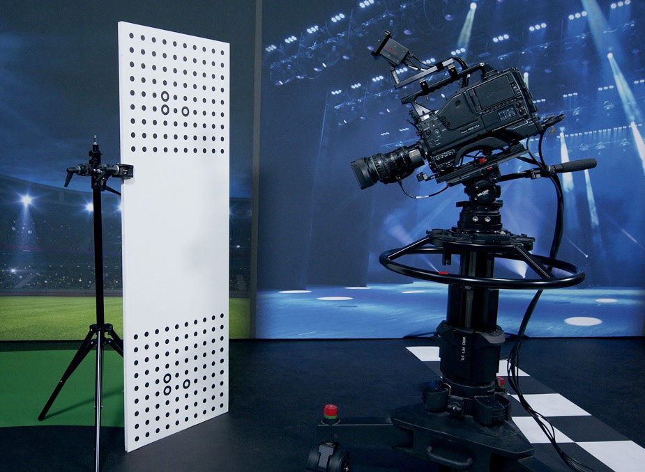
The camera offset is the difference in position and angle between the film camera (Chief) and the sensor camera (Worker).
When using a sensor camera, the Worker process will continuously calculate the pose of the sensor camera. Therefore, the offset between the sensor and film camera must be determined and added to the tracking data. The final tracking data will then represent the pose of the film camera.
The requirement for this is that sensor camera and film camera are mounted in such a way that their relative difference in position and angle does not change after the offset calibration.
If, for any reason, the position of the sensor camera to the film camera is manipulated after an offset calibration, the offset must be recalibrated.
2 Working Principle
The offset calibration is done by sampling and analyzing a calibration pattern in the Worker and Chief video at the same time. Multiple sample pictures of a calibration board are taken with the Offset Calculator software. The offset values of pan, tilt, roll, X, Y and Z are then calculated and can be saved into the Chief config file.
2.1 Calibration Patterns
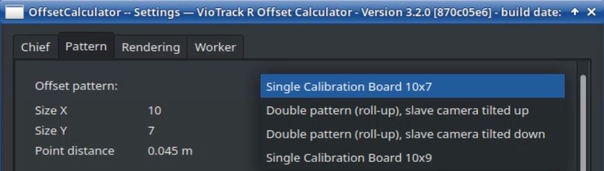
Depending on the angle difference between Worker and Chief camera either a single or double calibration pattern can be used. The patterns provided by Pixotope can be selected in the settings.
2.1.1 Single Calibration Board
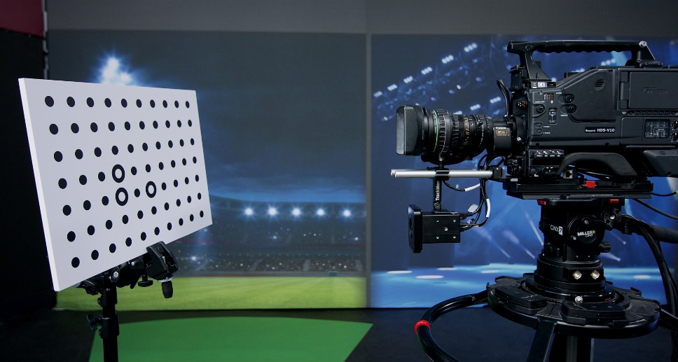
If Chief and Worker are facing the same direction, the same calibration board as for creating fixed lens calibration files can be used (single calibration pattern 10x7).
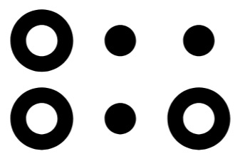
2.1.2 Double Calibration Board
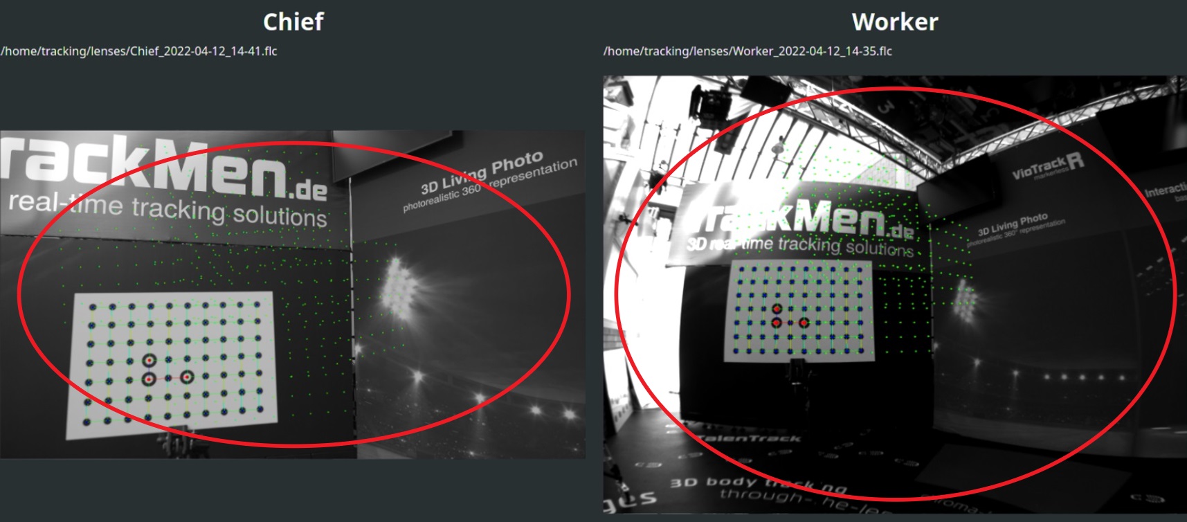
If the angle difference is so large that the single pattern can’t be fully visible in both cameras at the same time, a double pattern must be used.
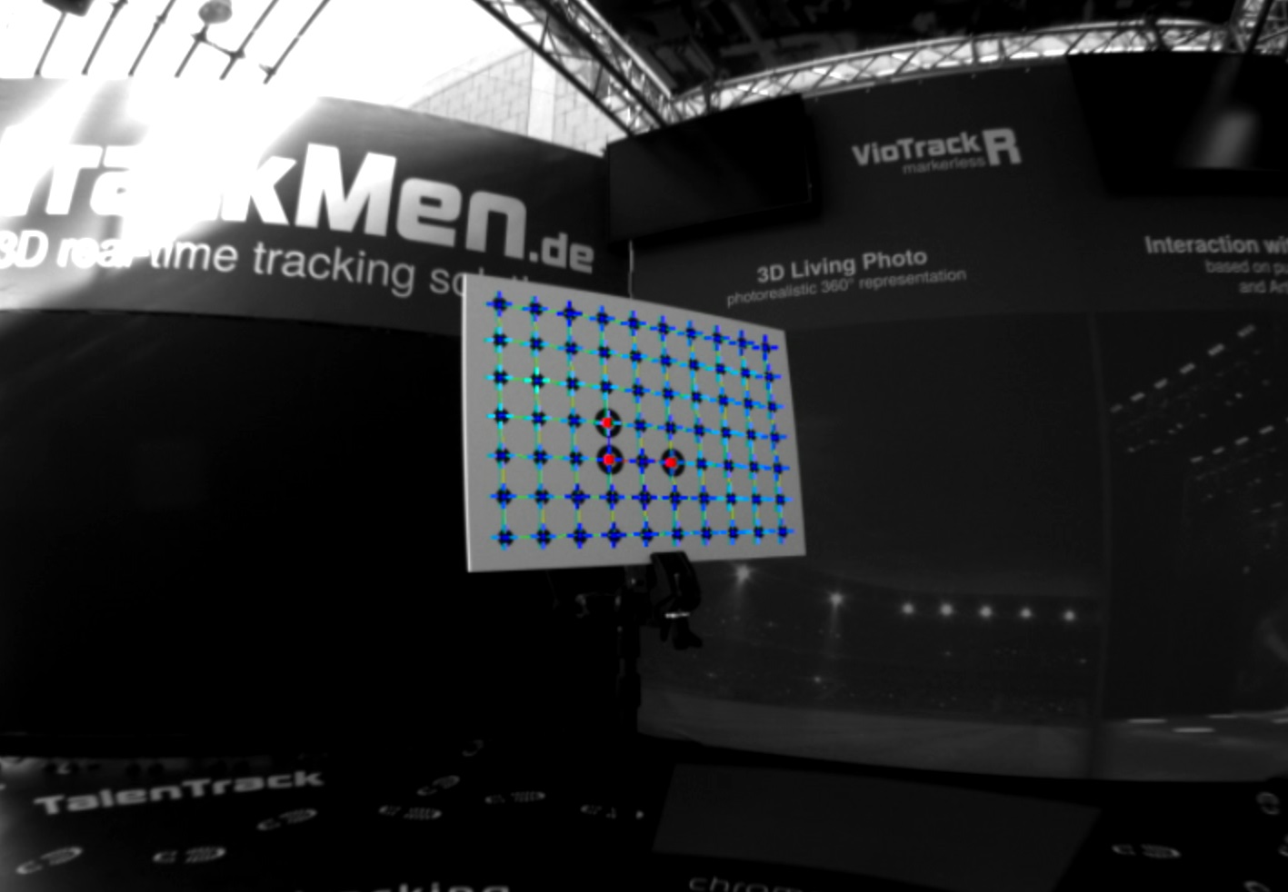
When using a double calibration pattern the alignment of the pattern is relevant. To have the board upright, the three circles must create an L-shape:
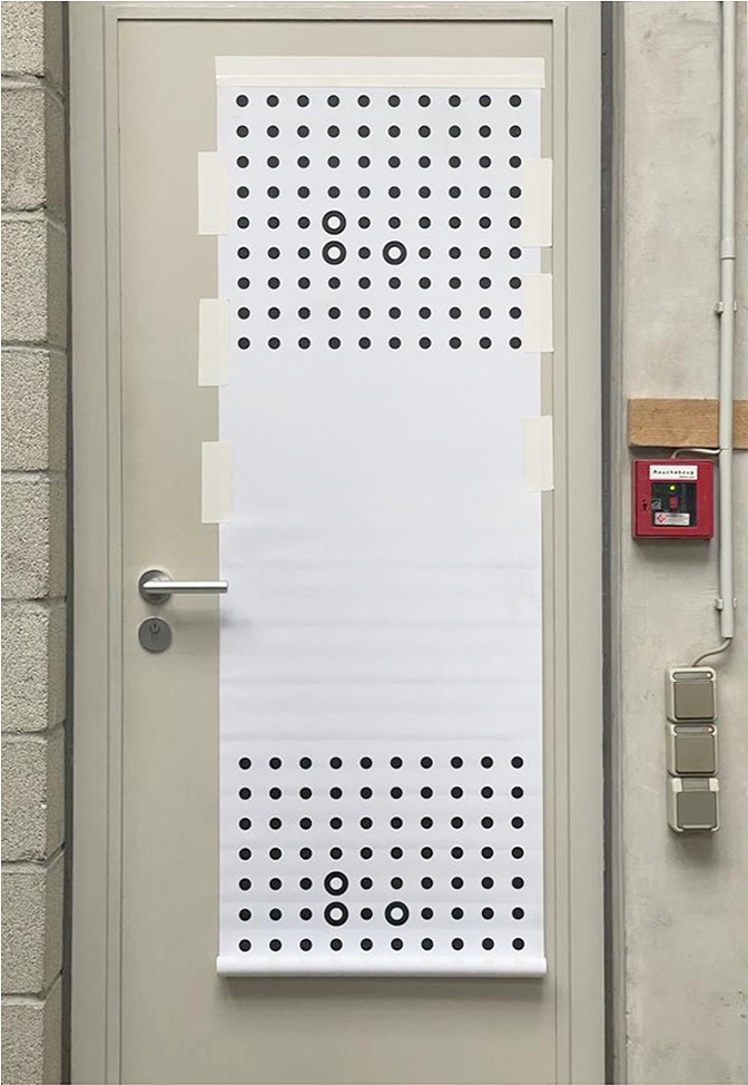
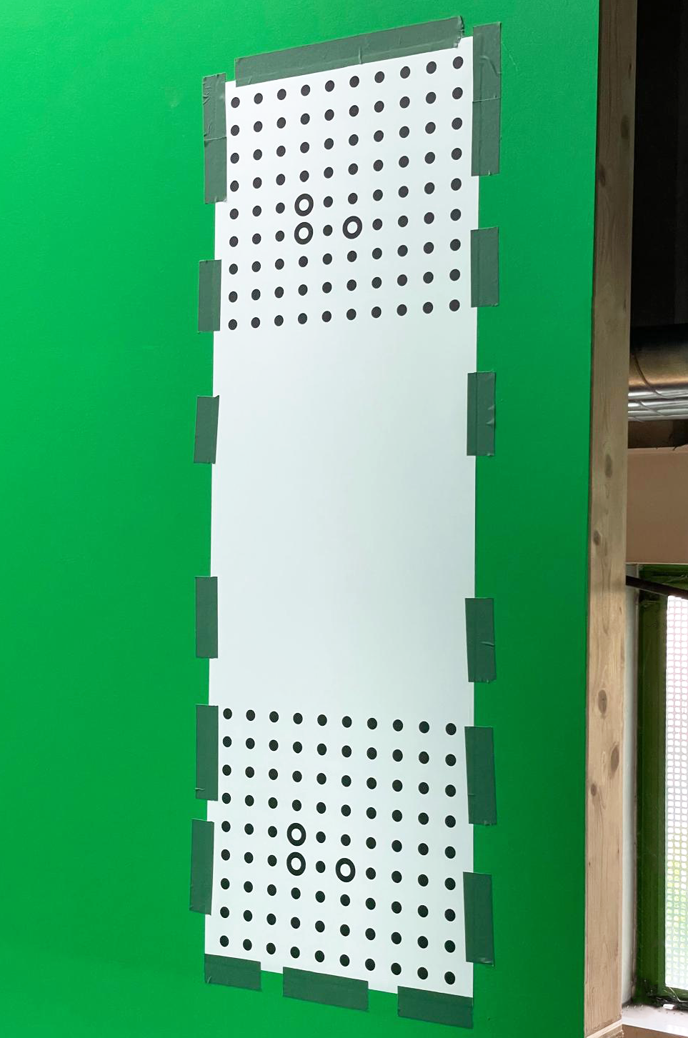
2.1.3 Roll-up Pattern
The Roll-up pattern refers to a double calibration pattern printed onto a flexible material that can be rolled up. This makes shipping and storing easier in comparison to a solid board.
When using this pattern in a studio environment, it needs to be stuck onto a flat and two-dimensional surface in reach of the camera. Since the calibration is based on the theoretically perfect pattern file, this setup requires increased care. Two aspects must be guaranteed:
-
The roll-up pattern must be perfectly two-dimensional
-
Surfaces like flat walls, metal or glass doors can be a good option
-
Look at them from the side to ensure they are not at all curved in both dimensions.
-
-
The roll-up pattern must be fully stretched in both dimensions
-
Start by taping the upper border of the pattern onto the surface
-
Stretch the material and add pieces of tape on the sides from top to bottom
-
No waves in the material should be visible as shown in illustration 5 in the lower half of the pattern. Ensure the material is not at all loose by pressing and moving your flat hand on the material. It should have no effect on the material
-
2.1.4 LED Wall Offset Calibration
With Pixotope Vision it is possible to calibrate the offset with the help of an LED wall. Check the respective video tutorial for more information. If the LED wall is curved this process is also possible but more complex, utilizing the Marker Pattern Generator and Marker Calibration software.
3 Calibrating the Offset
3.1 Setup
For calibrating the offset, fixed lens calibration files are necessary for both the Worker and the Chief.
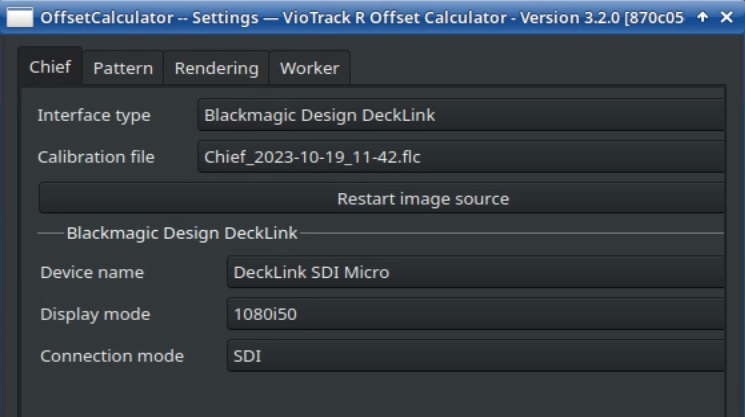
3.1.1 Chief
-
Start the Offset Calculator from the Tracking button in the task bar and open the Settings
-
Select the SDI video source and the correct video format for the Chief
-
Click Change image source
-
Select the correct lens calibration file for the Chief
-
Make sure the Chief camera lens is set to Wide Angle and Focus to ∞ during the entire offset calibration (the exact same physical lens settings that the FLC was made with)
-
Make sure to have a working Chief lens connection (test with lens data dump in the Chiefs lens tab)
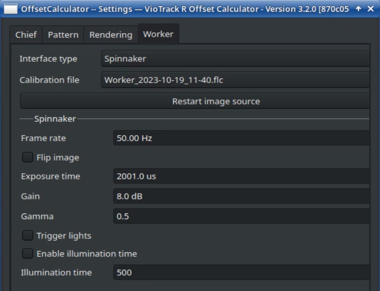
3.1.2 Worker
-
Navigate to the Worker tab
-
Select the sensor cameras Interface type and Click Change image source
More information on the sensor cameras video source can be found in chapter 3.1 of the Worker manual.
-
Select the correct lens calibration file for the Worker
-
Change Exposure time, Gain and Gamma to achieve a good visibility of the pattern
3.1.3 Calibration Pattern
-
Select the correct pattern in the Pattern tab of the settings
-
Place the calibration board upright in front of the camera in such a way that it does not move at all
Unlike to when doing a fixed lens calibration, the board can not be handheld when calibrating the offset. This is due to the fact, that Worker and Chief camera are not synchronized.
-
Make sure each camera can see only one target
-
Place the calibration board and camera in a bright area. If necessary adjust the Chiefs aperture, exposure time and gain and/or the Workers exposure time, gain and gamma to optimize the pattern recognition
In case the program has difficulties to recognize the pattern, you can change the Image rendermode to Segmenter in the Pattern tab. This will display the binarized image. The Threshold value can be adjusted to optimize the pattern recognition. The default value is 116.
3.2 Calibration Process
The goal of this process is to take between 8 and 16 samples and, after each sample, change:
-
the position of the camera in relation to the pattern (angle and distance)
-
the position of the pattern inside the video frame, but keeping it in the center area
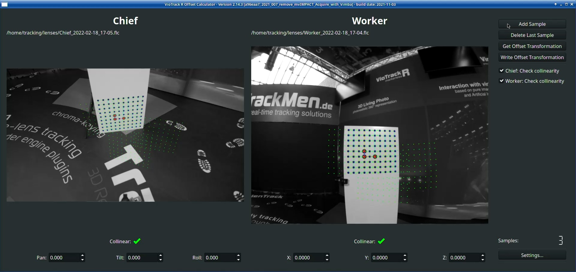
Green dots in the video will indicate where the pattern was during previously taken samples.
The collinearity check mark below the videos indicate if the pattern is well visible in its video. Samples can only be taken if both check marks are green. Vary distance to the pattern, image brightness or thresholds in case of false collinearity. If the collinearity stays false, check if the correct lens file is selected and the camera lens settings are correct.
-
Start by clicking on Add Sample while the pattern is in the middle of both images and the camera locked
When taking samples, the camera must be locked.
-
Take more samples varying the perspective between each sample by moving the camera
-
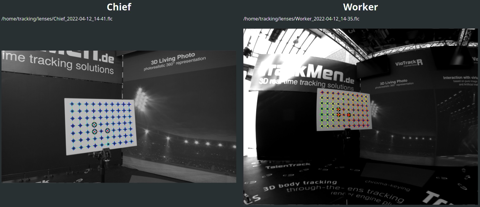
Avoid having the pattern in an edge or in a corner of either of the two frames. This is where the distortion is the strongest. Try to keep both patterns within the center area as indicated in illustration 11.
-
Also vary the position of the board within the red area, trying to spread the green dots inside the area. Do not take all samples with the board at the same position in the frame
-
Repeat the process until you have a minimum of 8 samples
-
Move the camera again without taking another sample
-
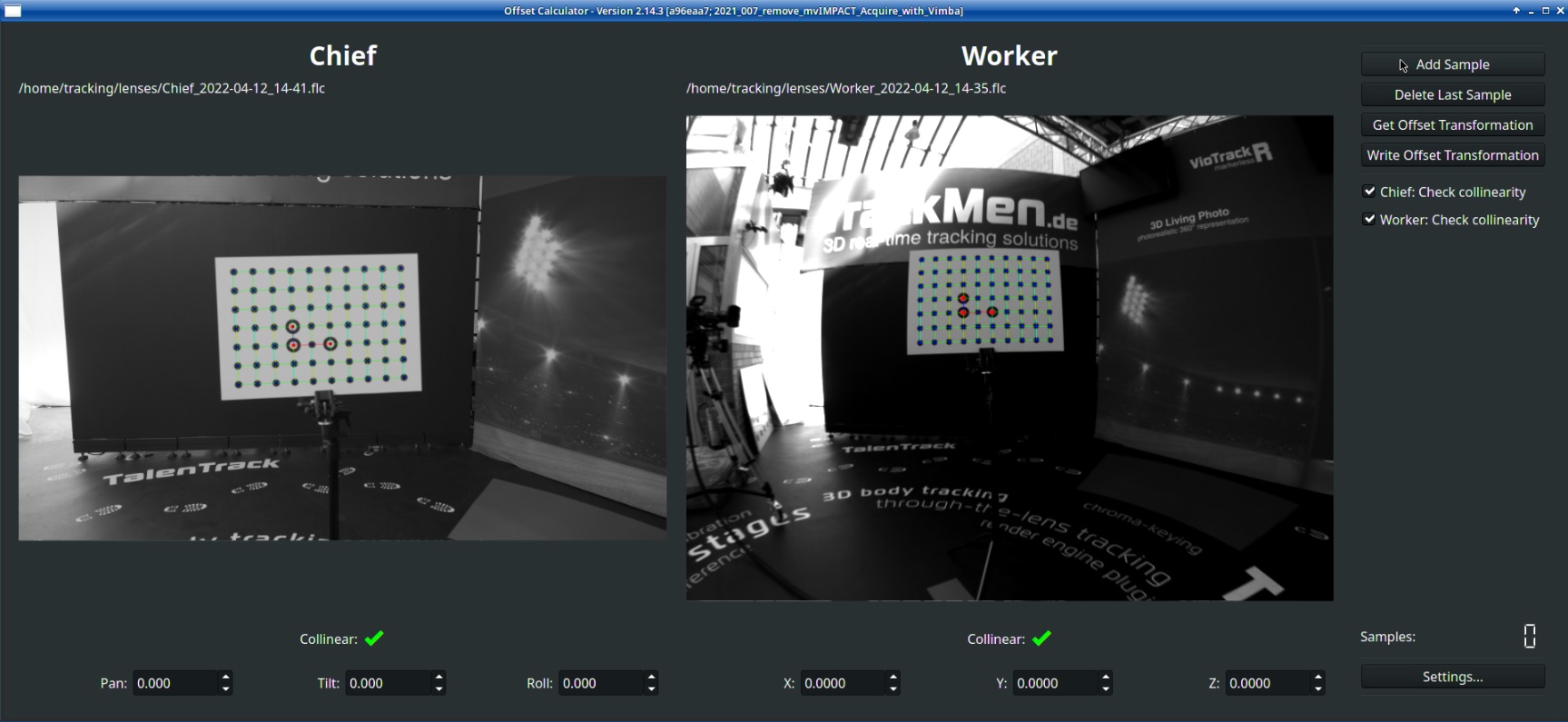
Click Get Offset Transformation. The Offset values will be calculated and displayed in the fields below the videos. A color code will indicate the quality of the offset calibration in the Worker video

-
Check the results from different camera perspectives:
-
In the middle region of the frame the colors should mostly be blue or green
-
Close to the edge of the frame the precision of the calibration is usually worse than in the middle
-
When you get a good result click Write Offset Transformation and select the pxVisionChief.cfg file to save the values into the Chief configuration
-
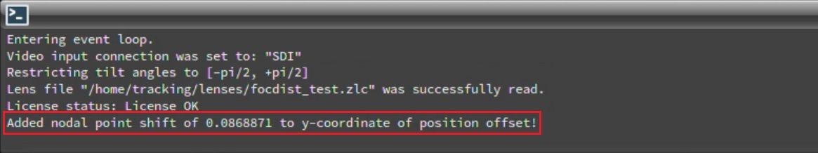
In case of using a zoom lens calibration file: Close the Offset Calculator and start the Chief. Check in the System Log that the Nodal Point Shift is being added to the offset values. This can only happen, if the lens connection is working while starting the Chief for the first time after the offset calibration