This guide presents a summarized manual version to go along with a personal training. It covers the basic steps of setting up a Pixotope camera tracking system with a sensor unit.
For more information and full manuals, please check the sub menus of Pixotope Vision.
1. Hardware Setup
Check out the video tutorial for cabling and inputs.
Standard Setup Diagram

Standard Data Flow Diagram

When?
-
Before system start
-
Fresh setup
Why?
-
Missing video stream
-
Zoom and Focus not working
-
Prediction not working (wrong delay)
What?
(Re)Start tracking Processes after changing connections!
-
Sensor Unit power: External DC adapter, connector to Chief camera 12V output or Power over Ethernet injector
-
Worker camera video: RJ45 ethernet connector to gigabit network port in PC
-
Chief camera video: HD-SDI connector to respective video capture card in PC, up to 1080p60 video. It may be taken from other sources like camera CCU or video matrix
-
Lens data connector:
-
Canon: 20-pin Hirose connector on lens “Remote1/Virtual” port to RS-422-to-USB-converter
-
Fujinon: 10-pin or 20-pin Hirose connector on lens “EXT” to RS-232 connector in PC or RS-232-to-USB-converter
-
External encoders: Encoders mounted at lens, connected to individual quadrature to USB adapters. One for zoom, one for focus
-
-
IMU Serial connector: optional: RJ45 serial connector to RS-422-to-USB-converter. If not working first time, try reconnecting on IMU side
-
Network connection to graphics engine: Ethernet connection, both PCs in same address space
2. Lens Calibration
Check out the video tutorial for Calibrating a fixed lens.
When?
-
After hardware check
-
Before Offset calibration: both cameras
-
Before initialization: Worker camera
Why?
-
Only if lenses have been manipulated after last calibration!
-
Unreliable tracking
-
Bad offset results

What?
-
Chief lens: make sure the zoom is set to wide angle and the focus to ∞
-
Worker lens: make sure the focus and aperture positions are set and fixed
-
Start Fixed Lens Calibration
-
Check calibration pattern detection. If incomplete, adjust Threshold in Settings
-
Click Add Sample to record pattern, covering all the image with green points step by step. Always hold the board at an angle towards the camera and never parallel to the camera chip
-
Check whether RMSE is below 1 and Maximum error below 5
-
Save the file

3. Offset Calibration
Check out the video tutorial about calibrating the offset.
When?
-
After lens calibration
-
Before tracking
Why?
-
Worker camera mounting has been manipulated
-
Origins in Worker video and Chief video do not match

What?
-
Make sure the Chief camera lens is set to Wide Angle and Focus to ∞
-
Make sure to have a working chief lens connection
-
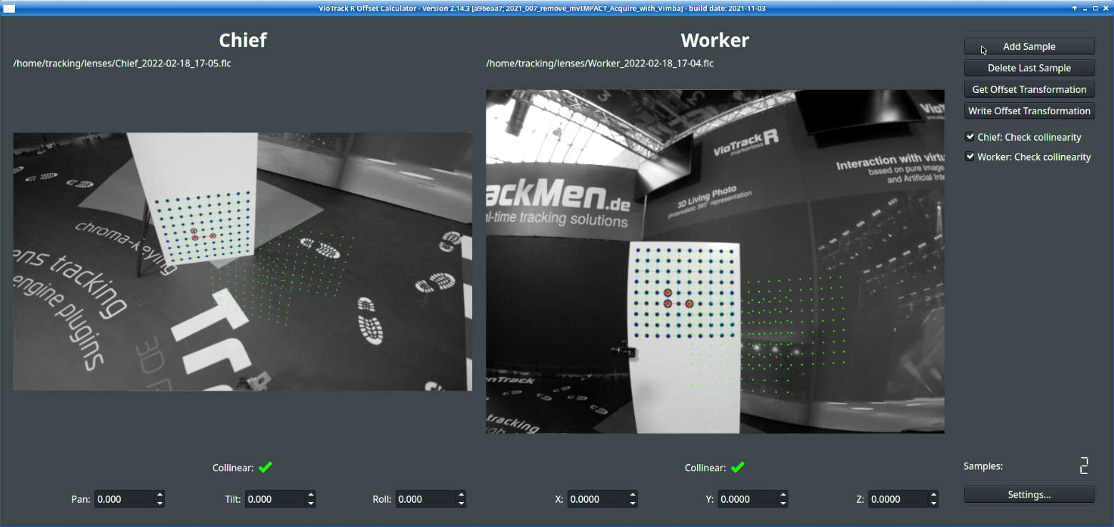
Start the Offset Calculator
-
Open the Settings
-
Select latest lens calibration files for both Chief and Worker in their respective tabs
-
Make sure to select the correct pattern in Pattern tab
-
Variant: in case of large offset angles between Chief and Worker camera, use a double-calibration target. Make sure it is positioned upright (as shown in Illustration 5, circles forming an L-shape) and the tilt direction of the Worker camera is correct
-
Take 8 Samples with varying perspectives onto the board. Make sure to have both the board and camera static when taking samples
-
Click Get Offset Transformation and check the result (mostly green and blue crosses displayed)
-
Click Write Offset Transformation and select the “pxVisionChief.cfg” file
-
Start the Chief and check that the Nodal Point Shift has been added in the System Log

4. Initialization
Please also refer to the initialization video tutorial, the ceiling reconstruction video tutorial and the Pixotope Fly video tutorial for a visual representation of the processes in this chapter.
4.1 Learning the environment
When?
-
After Worker lens calibration
-
Before tracking
Why?
-
New or significantly changed environment
-
New or revised Worker lens calibration
What?
-
Start the Worker
-
Open Settings and select the correct lens file In the Camera Tab
-
Set up the camera so the Worker camera can recognize as many objects in the scene as possible
-
Make sure to have an object in view that offers recognizable points in known distances, for example the 2.5m checkerboard target
-
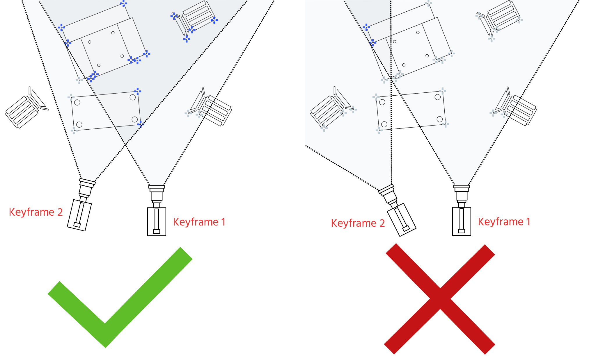
Click Set Keyframe
-
Move the camera sideways for about 30cm to 1m and click Set Keyframe again. If successful, reconstructed areas will appear blue
-
Move the camera around until the desired points for the coordinate system are reconstructed in 3D. New points will be added automatically for as long as “Allow Extension” option is checked


-
When all the area of camera movement is covered, uncheck Allow Extension option. Points will be reconstructed when reliably recognized from two different positions
-
Combine camera rotation with movement. Only panning or tilting does not provide proper 3D information
-
Keep enough reference in view: at least half the image should remain blue during rotation
4.2 Defining the orientation
When?
-
After collecting sufficient feature points
-
Before tracking
-
Does not apply to Auto-Init setups!
Why?
-
Define origin and orientation of coordinate system
-
In case of desired change of origin for graphics
-
In case of angle or size offsets
What?
-
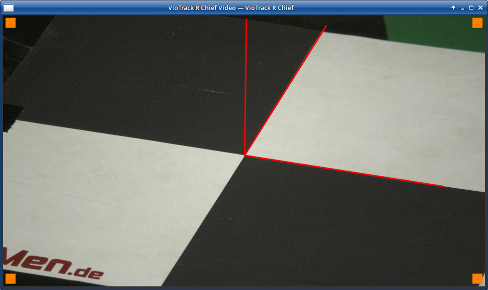
Choose 3 feature points to click on which are on the same plane (in most cases the floor)
-
Left mouse button: The first point defines the origin
-
Right mouse button: The second point defines the primary axis
-
Middle mouse button/wheel: The third point defines the secondary axis
-
Make sure to measure the exact distance between the first two points.
-
Adjust the primary and secondary Axis Settings as desired
-
Click Set Transformation
-
Enter the distance between origin and the point for the primary axis and click Set Distance
-
Click Save Reconstruction
In the Settings in the tab Rendering with active Show Expert Settings the dimensions of the grid can be changed.

5. Adjust Chief Lens Properties
5.1 Adjusting the Center Shift
Check out the video tutorial about adjusting the center shift.
When?
-
After first initialization
-
When graphics are visible and can be positioned in 3D space
Why?
-
Virtual objects shift on the ground when zooming
-
Chief camera lens has been dismounted
What?
-
Display the Cuboid in the Chief Video window
-
Place the cuboid on a distinctive real object for reference, for example the origin point
-
Zoom in all the way and center a corner of the Cuboid in the very middle of the picture
-
Lock the camera position, pan and tilt
-
Move the cuboid in the exact position using the Relocator
-
Zoom out all the way and watch the Cuboid move relatively to the real object
-
Use Center Shift X and Y values in the Chief Lens tab to correct the cuboid position
-
Zoom back in and out, check the result
-
If the Cuboid is in the correct position when zoomed in as well as when zoomed out, click Save
.png?cb=1fa8c7ca068e62a33edd24ef620f9722)

Remember to delete the Relocator values that you’ve been using for this step, since they were only useful to determine the center shift values with the zoom-method described in this chapter.
5.2 Adjusting the Fake Field Of View (Fake FOV)
Check out the video tutorial about creating an FoV table.
When?
-
After first initialization
-
When graphics are visible and can be positioned in 3D space
Why?
-
Change of lens or camera body
-
Different graphics engine or scene
What?
-
Place cuboid and camera as in chapter 5.1
-
Pan camera until cuboid is framed on the edge of the image
-
Check whether cuboid has shifted it’s position
-
In the Lens tab, adjust the Fake FoV until the cuboid looks the same as in the image center
-
Check result by panning and tilting the camera
-
Click Save
In case of a zoom lens this step has to be performed for multiple zoom steps as described in the FoV table manual.


Depending on graphics engine and version, the Center Shift may be processed differently.
-
Place a cuboid in the graphics engine in the same place as the Chief’s cuboid
-
Zoom in and out on the cuboid
-
If graphics still shift when zooming, go to the Chief Window Sender tab and try changing the Center Shift Scale Factor
Depending on engine setup and scene settings, the distortion may not be applied in the graphics output
-
Frame the cuboid and graphics cuboid near the edge of the image
-
In the lens tab, uncheck and check Use Distortion. Make sure both graphics make the same change in size/position
6. Setting the Tracking Delay
Check out the video tutorial about setting the delay.
When?
-
After successfully setting up tracking and initializing
Why?
-
Graphics and video do not move synchronously
-
Graphics do not move smoothly
What?
-
If implemented, check function of IMU: Chief --> IMU --> Dump IMU, check if numbers are being written in System log
-
In the graphics engine, place a virtual object near a real object
-
Pan the camera in short, quick movements, stopping a few seconds after each
-
In the Chief window, in the Delay tab, adjust the Sample Delay (ms) until graphics and video move synchronously. Do not lower Sample delay below 40ms. If it is not possible, add video delay on the graphics/keyer side
-
If implemented, it is possible to add Prediction (ms) in the IMU tab, reducing the tracking delay below 40ms
-
In the WorkerCam tab, adjust the Lens delay until graphics and video move synchronously in zoom and focus

The cuboid in the Chief Window, as well as the grid in the R Worker window both have their own delay which is different than that of the graphics engine! It is not possible to judge delay with them!
-
If the graphics do not move smoothly but jitter or jump from time to time, try various values for the Sample Delay (ms), between 1 and 20 [at 50Hz] until the graphics are smooth