1 Preface
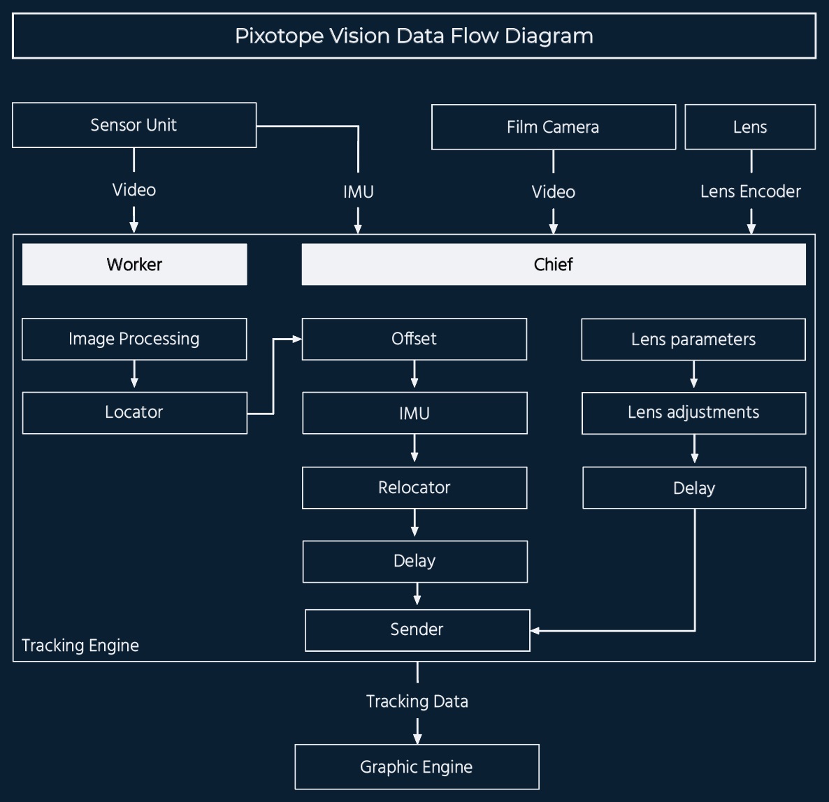
The Chief program is designed to process the data generated and forwarded by the Worker program enhancing them and adding data before sending the complete and final tracking data to the graphics engine.
The following settings need to be configured in the Chief software:
-
Software configuration to match the specific use case
-
Lens parameters
-
IMU
-
Sender
-
Delay
1.1 Working Principle
-
The Chief will take the position and orientation from the Worker and add the offset values. That way the tracking data will describe the pose of the film camera
-
The Chief leverages the motion sensor (IMU) inside each sensor unit to enhance the tracking data in regards of noise reduction and can decrease the tracking delay
-
The Relocator enables users to change the position and orientation of the world coordinate system.
-
Delay settings can be adjusted for synchronization
-
The lens parameters from the loaded lens file will be used to modify the tracking data for matching real and virtual world. If needed these values can also be adjusted
-
The Chief sends the final tracking data to one or multiple destinations. The desired format can be selected
2 Requirements for the Chief
2.1 Video input
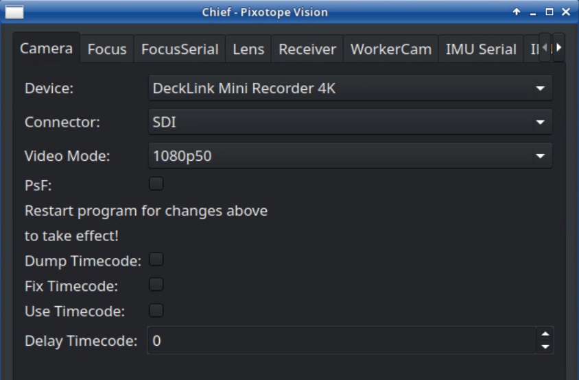
The Chief permanently needs the SDI video input of the film/broadcast camera. This is needed to synchronize the tracking data that are sent by the Chief to the correct frame rate. The software does not use external reference but uses the video's frame rate instead. Timecode can be embedded.
It should be undelayed and a clean feed, with no on screen menu items or other elements in it.
The Chief video is also needed during the calibration of the system as a reference. Therefore it needs to match the right lens file. After the calibration is finished, the video input can be any SDI input in the production formats frame rate.
Maximum video format depends on the capture card and can be downconverted.
2.2 Data input
2.2.1 Lens data
In case a zoom lens is being used for the tracked camera, the tracking engine needs to receive data that describes zoom and focus values in real time. Only that way it can calculate the corresponding optical parameters based on the respective Pixotope zoom lens calibration.
Pixotope Tracking provides different methods to receive lens data:
-
Canon and Fujinon serial interfaces are supported. The correct adapter will be provided and needs to be connected to the virtual output of the lens
-
Arri’s UMC4 interface for lens data is supported. The data will be transmitted from the UMC4 box over IP
-
The FreeD protocol can be used to transmit lens data to the Chief over IP or via a serial connection or over IP
-
Pixotope’s External Encoders can be mounted to the lens. These encoders will read the position of zoom and focus rings and forward the information to the tracking system. Mechanical cog wheel encoders and contact-free magnetic encoders are both possible solutions
The Pixotope Tracking can also work with non-zoom lenses such as prime lenses. The lens file can easily be created according to the fixed lens calibration manual.
This fixed lens setup can be combined with a single external encoder for the focus, either for defocusing effects for virtual elements or to compensate a significant focus breathing.
On the computers side a serial-to-USB converter is needed for the tracking engine to read this serial data stream over an USB port.
2.2.2 IMU data
The IMU in the sensor unit should be connected to the tracking engine with a quality ethernet cable no longer than 30 meters. Just like for the lens connection, a serial-to-USB converter is needed on the computers side for the tracking engine to read this serial data stream over an USB port.
If a longer cable connection to the IMU is necessary, Pixotope’s Signal Collector Box (SCB) can be used to extend the range. Also USB extenders can be used.
2.3 Lens file
In case a zoom lens is used, the correct zoom lens calibration file (ZLC) must be loaded onto the tracking engine into the /home/tracking/lenses folder. The zoom lens files can be downloaded from the https://pixotope.tfg.cloud/customer/user/downloads/48/lens.
A fixed lens calibration file can easily be created according to the fixed lens calibration manual.
3 Setup
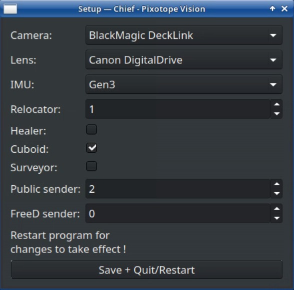
3.1 Chief Setup Menu
-
Start the Pixotope Chief
-
Click the Setup button on the bottom left corner. This will open the Setup window
-
Choose the appropriate configuration for the setup:
-
Camera: Select the right video I/O device. The standard use case, according to the system requirements is BlackMagic Decklink.
-
Lens: Select the right lens data interface. Lenses that output serial lens data are either Canon DigitalDrive or Fujinon DigiPower. Choose Fixed Lens for Pixotope Fly
-
IMU: Select the IMU generation. New models with Pixotope label are Gen3. Older models with a longer Sensor Unit casing and with TrackMen label are Gen2. When the wrong generation is selected no IMU data will be received
-
Relocator: One Relocator is recommended. In some cases more than one can be useful
-
Cuboid: Activate the Cuboid
-
Sender: Choose as many Senders as are needed
-
Healer and Surveyor: These tools are used by very advanced Pixotope tracking users
-
-
Click Save + Quit/Restart. This will restart the Chief with the new setup. The settings in the Chief itself will not be saved when doing this
3.2 Choosing Video Format
-
Select your Video I/O device, the Connector type (SDI or HDMI) and the production video format
-
Click Save and restart the Chief
-
The Pixotope Vision Video window should now display the live video
3.3 Selecting Serial connections
Connect only one of the serial-to-USB converters to the tracking engine and proceed with one of the steps below. In case external encoders are used, skip chapter 3.3.1.
3.3.1 Lens Serial
-
Connect the Lens serial-to-USB converter to the tracking engine
-
Navigate to the Lens tab
-
Click Rescan and select the device
-
Click Save and restart the Chief
-
Navigate to the Lens tab and activate Dump Parameters
-
Check if the lens data is being dumped in the SystemLog
Lens data can only be dumped when the Chief is receiving a video input!
3.3.2 IMU Serial
-
Connect the IMU serial-to-USB converter to the tracking engine
-
Navigate to the IMU tab
-
Click Rescan and select the device
-
Click Save and restart the Chief
-
Navigate to the IMU tab and activate Dump IMU
-
Control if the IMU data are being dumped in the System Log
3.3.3 Zoom and Focus Serial
In case external encoders are used, do the following:
-
Connect either the zoom or the focus serial-to-USB converter to the tracking engine
-
Navigate to the appropriate tab
-
Click Rescan and select the device
-
If both zoom and focus encoders are used: Repeat the steps above for the other device
-
Click Save and restart the Chief
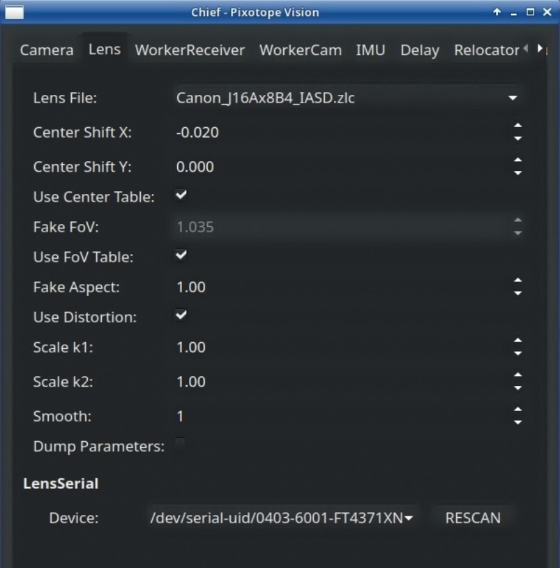
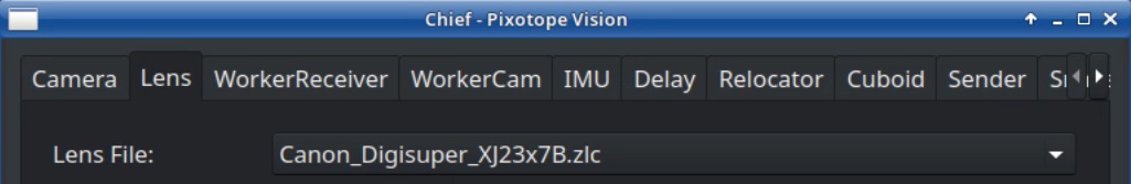
3.4 Selecting Lens File
-
Select the correct lens file in the Lens tab
-
Click Save
Lens files are stored in /home/tracking/lenses. Zoom lens files are provided by Pixotope.
4 Operation
Calibrating the Chief, as described in this chapter, has the following prerequisites:
-
The Worker is set up and tracking
-
The Offset between Worker and Chief camera has been calibrated
-
IMU data are received by the Chief
-
Lens data are received by the Chief (in case zoom lens or external encoders are used)
-
The correct Lens file has been selected
-
SDI video of the film camera is received by the Chief and displayed in the Chief Video window
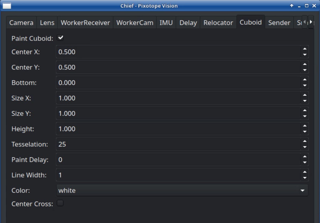
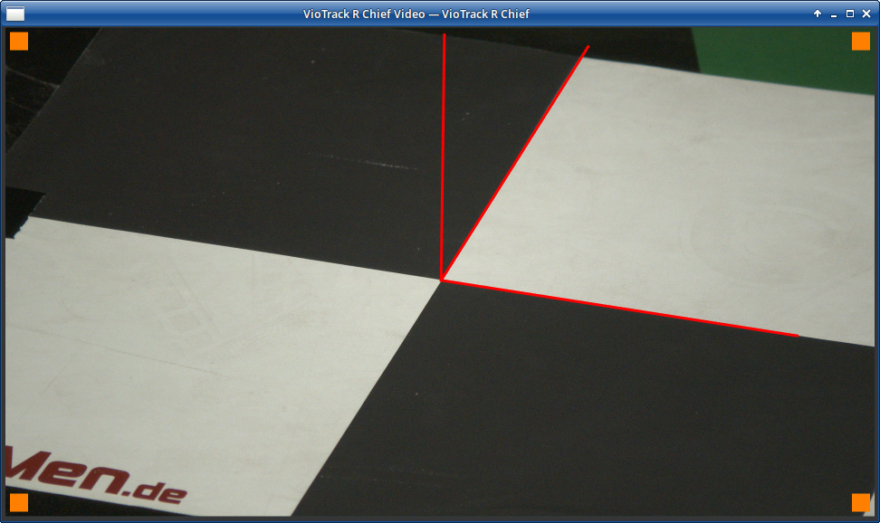
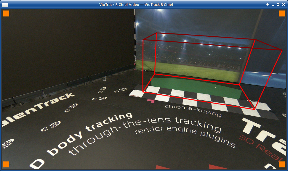
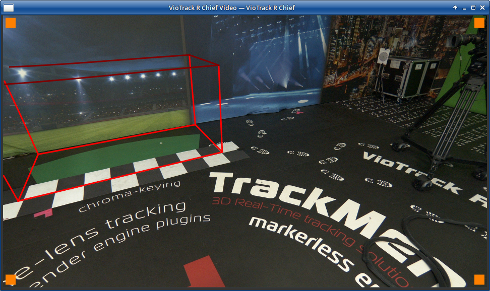
4.1 Cuboid
In order to visualize and examine the tracking data, a composition of video and virtual object is needed. The Chief’s Cuboid serves as a virtual and three-dimensional reference object. It is painted onto the Chief video, meaning that the final tracking data can be examined independently from the graphic engine.
The Cuboid will be placed with its center on the floor plane (X, Y) and on the coordinate-systems origin. The Cuboids center is in the middle of its bottom side. To see how well the Cuboid fits to the origin point, the Center X and Center Y values need to be half the size of the Cuboids Size X and Size Y. This way a bottom corner of the Cuboid sits directly on the origin.
-
Navigate to the Cuboid Tab
-
Activate Paint Cuboid
-
Set Size, Center, Bottom and Height to fit the use case
-
Choose Line Width and Color for good visibility
-
Move the camera quickly and set the optimal Paint Delay
The Paint Delay only affects the Cuboid and not the tracking data output.
4.2 Center Shift
The center shift represents the physical deviation of the lenses center to the actual camera chips center. In theory the image center is in the exact middle of the frame. But in reality there is a more or less small deviation from the theoretical center that is unavoidable due to imperfect lens mounting. The easiest way to make this effect visible is when zooming in and out on a virtual object. The object will seemingly move position when zooming. By adjusting the Center Shift, this effect can be removed.
Since no mounting of a lens to a camera body can be physically perfect, the Center Shift values should be controlled every time the lens has been detached from the camera, even if it is the same lens.
-
Navigate to the Cuboid tab and activate Paint Cuboid
-
Zoom in all the way, center a real object point (for example the origin mark) in the center of the image and adjust the focus
-
Use the Center Cross in the Cuboid tab to help finding the center of the image
-
Lock the camera (position, pan and tilt)
-
Use the Relocator to position a corner of the Cuboid exactly on the real object point
-
Zoom out all the way
-
If the Cuboid has changed its position relative to the real object point while zooming, the Center Shift values need to be adjusted
-
Navigate to the Lens tab and use Center Shift X and Y values to correct the Cuboid position
-
Zoom back in and check the result
-
If the Cuboid position is not exactly on the real object point again, repeat the steps from step 5 onward

-
If the Cuboid is in the correct position when zoomed in as well as when zoomed out, click Save
Remember to delete the Relocator values that you’ve been using for this step, since they were only useful to determine the center shift values with the zoom-method described in this chapter!
4.3 Field of View (FoV)
The field of view is a property that is a visible symmetrical deviation more apparent on the edges of the image and not at all visible in the image center. By adjusting the Scale FoV value (formerly Fake FoV), a false focal length can be corrected. The Scale FoV value is global, meaning that it affects all zoom positions equally. Discrepancies in the FoV usually differ between the zoom stages. For FoV adjustments over the entire zoom range, a Correcions File (formerly FoV table) needs to be created (chapter 4.3.1).
Adjusting the FoV should only be done after adjusting the Center Shift. If the Center Shift value is incorrect this translates in an asymmetrical distortion in the FOV and will result in incorrect values.
Similar to the Center Shift, every time that the lens has been detached from the camera body the FoV values need to be controlled, even if it is the same lens. This is due to imperfections in the physical lens mounting of every camera.
-
Place the Cuboid on a real object as in chapter 4.2 without using any Relocator (preferably the origin point)
-
Place the camera far away from the Cuboids position
-
Pan camera until a corner of the Cuboid is framed on the edge of the image
-
Check whether a corner of the Cuboid has shifted its position
-
In the Lens tab, adjust the Scale FoV until the corner of the cuboid sits on the correct position

-
Check the result by panning the camera. The position of a virtual object should not change when panning or tilting the camera
4.3.1 Corrections File (FoV Table)
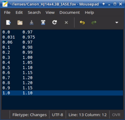
For creating an Corrections File the correct FoV values need to be determined for a number of zoom steps between fully zoomed in and fully zoomed out. These values are written into a table file. The Chief interpolates between these values while the lens is zooming.
-
Make sure that tracking is working properly, the Chief is receiving lens data and the Center Shift has been adjusted
-
Place the Cuboid as in the previous chapter and make sure it is sitting correctly
The FoV has no effect in the image center. So even without any FoV adjustments the correct placement of a virtual object can be determined in the image center.
-
Place the camera far away from the Cuboids position
-
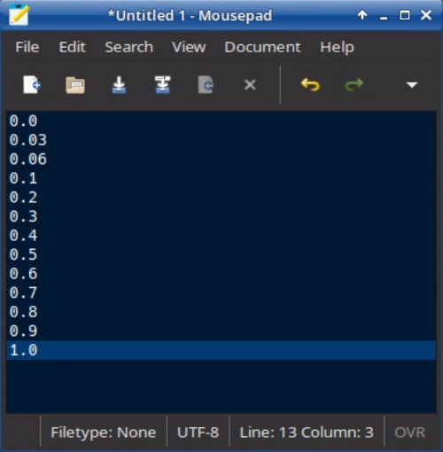
Click on the operating systems Menu button and open the Text Editor
-
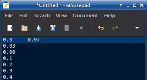
Enter a number of sample values from 0 to 1 in 0.1 step, each value in a new line. For a better resolution in the wide angle area, add 0.03 and 0.06
-
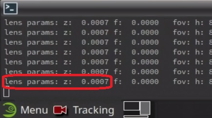
Go to the Lens tab and activate the Dump Parameters option. The incoming data from the lens, as well
as the calculated values, will be written in the System Log. -
Find the zoom parameter (z: …), which represents the lenses zoom position, normalized to a value between 0 (wide angle) and 1 (zoomed in)
-
Zoom out fully to the physical limit of the lens
-
Find the correct Scale FoV value for this zoom position just like in the previous chapter 4.3
-
In the text editor click behind the 0.0 in the first line and press the tabulator key or the space bar
-
Type in the FoV value
-
Zoom in until the zoom parameter is approximately 0.03
-
Find the correct FoV value for this zoom position
-
Repeat these steps until a value is determined for each step
-
Save this text document in the folder /home/tracking/lenses with the same name as the zoom lens calibration file which is being used, but with the ending .fov instead of .zlc
-
Activate Use Corrections File in the Lens tab
Activating the Use Corrections File option will overwrite any Scale FoV setting for as long as it is checked.
-
Save and restart the Chief
-
Check for a line in the system log: “Corrections table correctly read”
-
Control if the FoV values are correctly applied in each zoom step
-
If the FoV is incorrect at a certain zoom step, another table entry can be created. Add the entry of this zoom step value in the table and disable Use FoV Table to determine the correct FoV value
4.4 Sender
The Sender Tab is where you can define where to forward the tracking data to as well as control parameters to match the desired graphics engine.
You can have multiple Sender tabs sending to different IP’s and graphics vendors. The amount of Senders and FreeD Senders in the Chief is determined in the Chiefs Setup (chapter 3.1).
-
Insert the IP of the graphics engine in Host and choose a port to send to
-
Select one of the presets from the dropdown menu corresponding to your graphics engine vendor
-
As soon as IP and port are entered, the tracking data are constantly being sent to this address
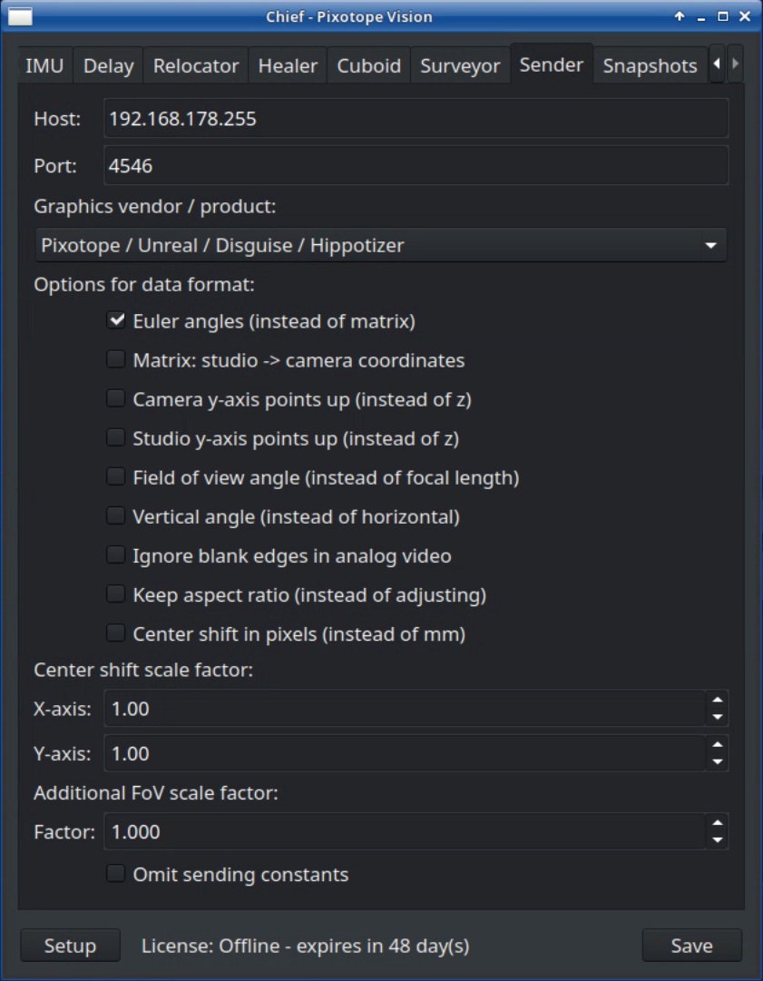
A Host IP that ends with .255 is a broadcast Sender, that sends to all IPs in that range.
4.5 Delay
Setting the Delay
To visualize the delay between graphical elements and the real world video content, you need to see both at the same time in the graphics engine output. The easiest way to set the delay is to place an AR object on a real world reference object, for example on the Pixotope checkerboard on the floor.
The final delay can’t be adjusted with the cuboid in the Chief video. It has a different delay than the graphic engine and can be adjusted with the Paint Delay in the Cuboid tab.
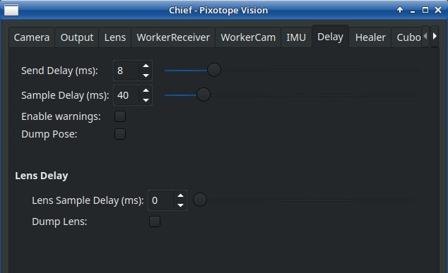
There are four different delay settings as described in the following chapters. Begin by opening the Delay tab of the Chief window to adjust Sample and Send Delay.
4.5.1 Sample Delay
The Sample Delay is used to synchronize graphical elements and real world video content. It is not purely a delay, but also includes the processing time of the tracking. The minimum value for the Sample Delay is 40ms for Pixotope Tracking.
In order to effectively adjust the delay of video and tracking, the following procedure is recommended:
-
Set the minimum value for Sample Delay (40ms)
-
Do quick and short pans to find out whether the real world video content is lagging or the graphical elements
-
Set a video delay in frames on the keyer or in the graphic engine so that the graphics are slightly ahead
-
Gradually increase the Sample Delay until the graphical elements are synchronized with the video
4.5.2 Send Delay
The Send Delay adjusts the sending time within a frame to adjust to the clock of the graphics engine. If the graphic jitters or jumps when slowly panning, gradually increase the Send Delay until the effect disappears. If no such effect is visible, it can be left at the default value of 8ms.
The value 0ms is the exact beginning of the frame. If the video format is for example 50Hz, 20ms would have the same effect as 0ms. That means a value between 0 and 20ms had to be found.
4.5.3 IMU Prediction
Using the IMU as an additional sensor, a movement prediction can be made to reduce the total delay for the tracking data. This is done with the Predict (ms) setting in the IMU tab, described in the next chapter.
4.5.4 Lens Delay
The serial lens data stream is collected via separate encoders and therefore has its own delay setting (see Illustration 1).
Adjust the Lens Delay value using quick and small zoom changes.
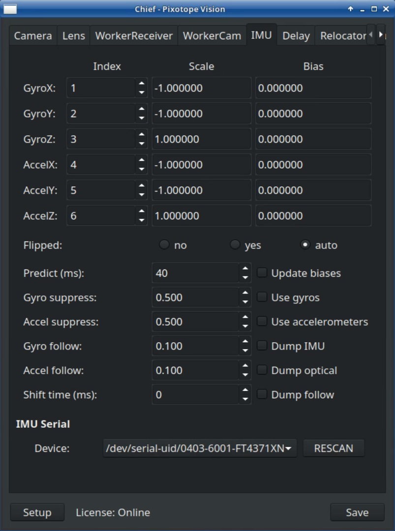
4.6 IMU
The IMU tab controls the behavior of the Inertial Measurement Unit which is built in the Sensor Unit case. The IMU has two purposes:
-
Reducing data noise in the tracking data. This removes shaking in graphical elements which might be visible when zooming in on them
-
Reducing tracking delay by predicting the direction of camera movement
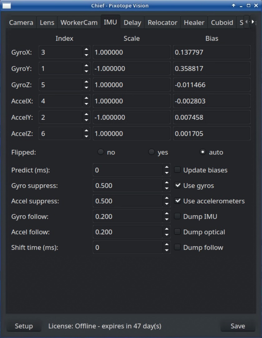
4.6.1 Activation
Index and Scale values are automatically set correctly when you choose the IMU generation in the Setup (see chapter 3.1).
In order to use the IMU, the following steps need to be taken:
-
Activate Dump IMU and check the System Log to see if the IMU data are received
-
Lock the camera so that the Sensor Unit is completely still
-
Activate Update Biases for one or a few seconds. This enters the Bias values
-
Activate Use gyros and Use accelerometers and deactivate Dump IMU
-
Save
4.6.2 Suppress
The suppress values determine the threshold where noise in the data is removed by the IMU. There is a value above which an increase has no effect anymore. Usually default values (0.500 or 0.600) don’t need to be changed.
4.6.3 Follow
The follow values determine the amount of influence the IMU has on the tracking data. A higher value means a lower influence of the IMU. 1.0 means that no IMU data is used. This means for visibly negative effects of the IMU these values need to be increased. Usually the default value 0.100 does not need to be changed.
If graphical elements visibly change/correct their position after a movement has stopped, this effect can potentially be removed by increasing Gyro follow and Accel follow for example to 0.200.
4.6.4 Prediction
An increase in this value will result in tracking data being sent with less delay. The minimum value is 0 (tracking delay = Sample Delay). The upper limit depends on the setting of the Sample Delay in the Delay tab. Exceeding the value of the Sample Delay will cause no change in the total tracking delay.
That means by setting a minimum Sample Delay of 40ms and increasing the Prediction value the total tracking delay is getting closer to zero.
4.7 Modifying Tracking
Adjusting the tracking after a correct setup is not needed. As a user there are two ways of modifying the tracking data in regards of position and orientation:
-
With the Relocator position and orientation of the tracking world coordinate system can be adjusted. Pos X,Y and Z move this coordinate system along the axes defined in the reconstruction. Pan, Tilt and Roll change the axes angles around the studio origin. Pan rotates the world around the Z-axis (pointing up), Tilt rotates the world around the X-axis (pointing to the right) and Roll rotates the world around the Y-axis (pointing forward).
-
The Adjust Chief settings in the WorkerCam tab modify the offset values. Pos X,Y and Z move the camera coordinate system along its axes. Pan, Tilt and Roll changes the axis angles around the cameras nodal point. The camera is pointed along the camera Y-axis. A Pan of 10 degrees would shift all virtual objects permanently to the right within the perspective of the camera, no matter where the camera is positioned.
To put it simple: the Relocator moves virtual objects in the studio in relation to the studio coordinate system whereas adjusting the Chief moves virtual objects in relation to the camera. Keep in mind that Adjusting the Chief modifies the offset values, which were calibrated before. If these values seem to improve the precision, it should be considered to recalibrate the offset. Otherwise adjusting the Chief values should not exceed changes higher than a few centimeters and or more than 1 degree.
If position or orientation of the tracking are not as expected, all calibration steps should be controlled and where required redone before adjusting with a Relocator or the Adjust Chief settings.