1 Preface
Pixotope camera tracking systems work with two different lens calibration types that map the parameters of the lens’ projection on the chip and compile them for the graphics engine. Commonly used are zoom lens calibrations (ZLC). Prime lenses require less measurements due to the fixed focal length. They can be calibrated quickly with the included software called Fixed Lens Calibration (FLC).
This document is a guide about how to create a fixed lens calibration for a prime lens for the use as a Pixotope Vision/Marker Chief lens calibration file. As these lenses are likely to have to change the focus during operation, the lens breathe has to be taken into account. This means the change of parameters, mainly field of view and distortion, during focus operation. Furthermore, the varying focus distances may be measured if it is desired to apply defocus to the graphics.
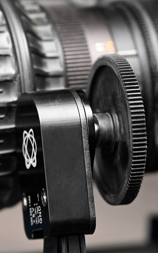
This guide covers only the differences of calibrating variable focus for a FLC file. It is directed at experienced users who know the basics already. The process requires a fully operational Pixotope Vision or Marker system with an external lens encoder for the focus ring.
The manual for creating a fixed lens calibration can be found here.
1.1 Working Principle
A proper calibration will be done for multiple focus ring settings. Each calibration captures lens parameters like distortion, field of view and image center. The system will interpolate between these calibrations when the focus is changed. Both end stops, Infinity and MOD, must always be calibrated.
2 Variable Focus Calibration
2.1 Preparations
2.1.1 Preparations - Chief
-
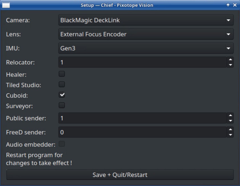
Start Pixotope Vision or Marker Chief
-
Select External Focus Encoder under Lens and click Save + Quit/Restart
-
In the Chief window, switch to the Focus tab and select the USB converter of the focus encoder that is connected to the computer
-
Save and restart
-
Check the Dump counter option in the Focus tab. The system log will print the encoder values, abs meaning the raw encoder counter while rel shows the normalized value between 0 and 1
-
Change focus all the way, from infinite to minimum object distance and back, to teach the system the minimum and maximum range
-
When the focus of the lens is set to infinite all the way, the rel-value should be 0. When the focus of the lens is set to minimum object distance all the way, the rel-value should be 1. If these values are swapped, you can activate Invert counting direction. You would need to repeat steps 3 to 5 in that case
Make sure to have the infinite and the MOD measurement at the absolute end of the focus ring range, not at the marking on the lens. Most lenses exceed these markings by a bit, so rotate the ring until it meets its complete stop.
Note that the relative value for Maximum and Minimum may not be exactly 0 and 1, but values very close to it, like 1.2875e-5 and 0.99997.
-
Save and close the Chief using the AppManager Stop button
2.1.2 Preparations - Focus Distance Editor
-
Open the Software Manager. The root password is: tmgmbh51105k
-
Go to Configurations and to Repositories
-
Activate Enable and Automatically Refresh of the openSUSE.org Repository and click OK
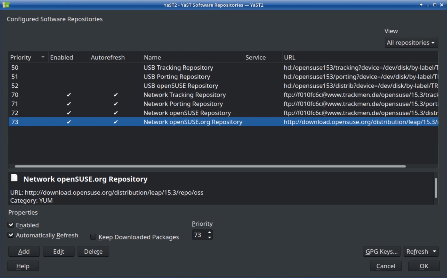
-
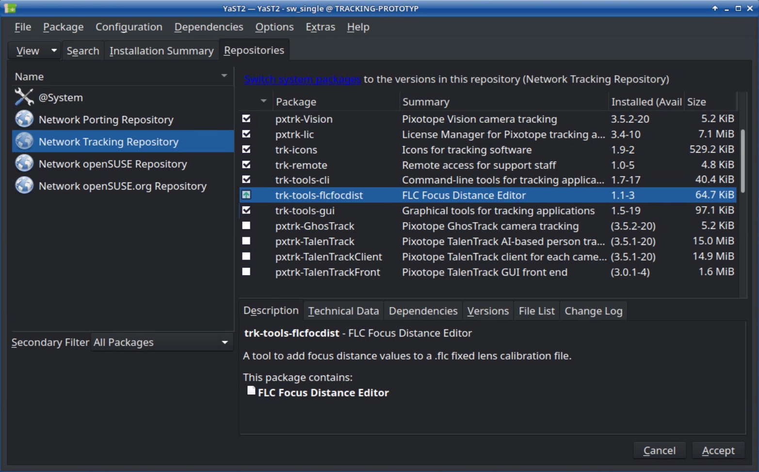
Go to Repositories and to Network Tracking Repository
-
Install the trk-tools-flcfocdist package and also make sure that the trk-tools-cli and trk-tools-gui packages are up to date
-
Click Accept
-
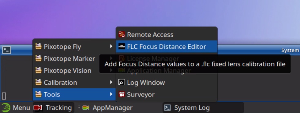
Open the FLC Focus Distance Editor
-
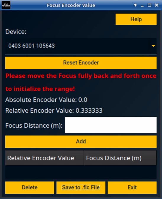
It will automatically select the USB converter for the focus encoder as Device based on the setting saved in the Chief config file
-
It will also remind you to initialize by turning the focus ring from end to end. Go ahead and do this
2.1.3 Preparations - Fixed Lens Calibration Program
-
Start the Fixed Lens Calibration program while leaving the FLC Focus Distance Editor running
-
If necessary set the right settings in the Camera and Pattern tab
As the image may be defocused in calibration pattern distance, it is recommended to close the iris as far as possible to have maximum depth of field. That can make it necessary to increase the brightness of the environment and/or the gain of the camera
-
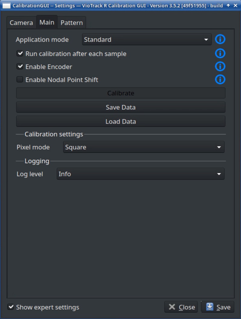
Open the settings and activate Show expert settings. Then switch to the Main tab and check the Enable Encoder option. Save, close and restart the program to apply
2.1.4 Preparations - Determining Focus Ring Positions
Define a number of focus positions that you want to calibrate. For each of these focus ring positions a lens calibration will be done. The system will interpolate between these calibrations when the focus is changed. Both end stops, Infinity and MOD, must always be calibrated.
Four should suffice for a lens with little parameter change during focus operation. Increase the number for lenses with more severe changes in field of view and/or distortion.
In this example, four focus settings will be used making it these focus positions:
encoder rel-value: 0.0 (Infinity)
encoder rel-value: 0.333
encoder rel-value: 0.667
encoder rel-value: 1.0 (MOD)
2.2 Capturing Multiple Focus Positions
-
Have both, Fixed Lens Calibration and Focus Distance Editor running
-
Set the focus ring to the Infinity end stop for the first calibration run
-
For the first calibration run, with the focus set to Infinity, leave the Encoder value at 0.0 and perform a lens calibration as usual
-
Save the first calibration for the Infinity end stop twice. One file will only be used for the offset calibration between Chief and Worker later on. The other one will be the one that contains multiple calibrations
-
Click Save and enter a filename recognizable for the offset calibration in the upcoming dialog box. Then click save (example: “Prime_20mm_FullHD_Offset”)
-
Click Save again, this time entering a file name that can be recognized as having multiple focus positions calibrated (example: “Prime_20mm_FullHD_VariableFocus”)
-
-
Close and restart the Fixed Lens Calibration program
-
Set the next focus ring position on the lens. In our example this is the Encoder value 0.333. The Focus Distance Editor can be used to approximate this position
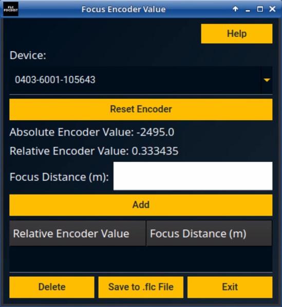
-
On the right side of the calibration window, check the Append calibration option
-
Enter the current Relative Encoder Value in Encoder value
-
Perform another lens calibration as usual
-
Click Save. This time, a dialog box will open, offering to choose a calibration file from existing lens calibrations
-
Choose the file saved for multiple focus calibrations (example: “Prime_20mm_FullHD_VariableFocus”) and confirm with Save
-
Repeat steps 5 to 11 until all focus positions have been calibrated and saved into the same calibration file
-
Close the Fixed Lens Calibration program
3 Focus distances
In order to apply defocus to virtual graphical elements, the system needs to calculate a focal plane and forward it to the graphics engine. It uses the focus encoder to know what the lens’ focus is set to.
For this to work precisely, the focus distances need to be measured and added to the lens calibration file.
3.1 Preparations
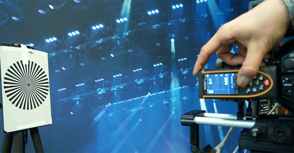
The distance measurements will be done by focusing an object in various distances and noting down the corresponding encoder value. As an object, a Siemens star is optimal to judge the exact focus setting. Besides that, the aperture should be closed to have a smaller depth of field and thereby making it clearer to determine the right focus setting.
Either the object or the camera must be able to be moved, so various distances can easily be created. Depending on the focal length of the lens, a large area may be necessary to provide enough samples.
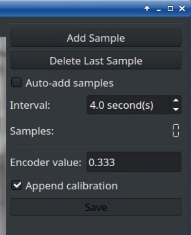
3.2 Measuring the focus distances
-
Start the FLC Focus Distance Editor
-
Initialize by turning the focus ring from end to end
-
Set the focus to minimum object distance (MOD). The encoder value should now be 1
-
Place the Siemens star in front of the camera and move it closer to the camera until it is in perfect focus
-
Measure the distance between flange of the camera and the object
-
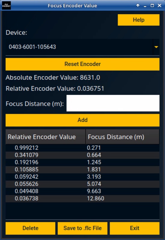
Write the distance into the Focus Distance (m) field in the Focus Distance Editor and click the Add button
-
Move the object away a bit. For example to roughly 1m. Measure that distance to the camera flange
-
Focus the object and add the second pair of distance and encoder value
-
Repeat with multiple distances. The number of distances vary with the type of lens. Around 10 will surely suffice for a prime lens
Quick and dirty: If there is no time to take the measurements or the precision is not of importance, you may choose to trust the markings on the lens that give the focus distances. Just position the focus ring to a distance marked on the lens, type in this distance in meters and click Add.
-
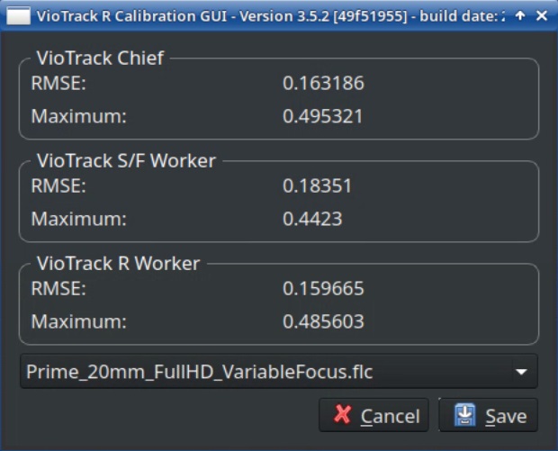
Click Save to .flc File and select the file with the multiple focus calibrations (example: “Prime_20mm_FullHD_VariableFocus”)
-
It can then be chosen to add a suffix to the filename to indicate that this file has focus distance values in it
-
Start the Chief and go to the Lens tab
-
Select the lens file that was just saved
-
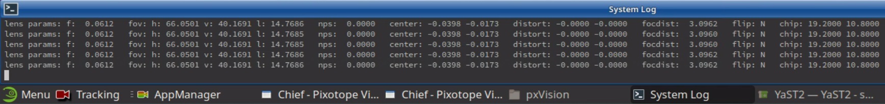
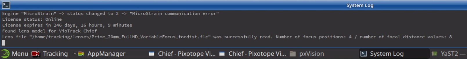
The System Log will print a message that states if the lens file was correctly loaded and how many focus position calibrations and how many focal distance values are in this lens file
-
Activate the Dump
-
The System Log will continuously print the current lens data including the focal distance (focdist)