1 Preface
For optical camera tracking the individual characteristics of a lens have to be calibrated. The lens calibration maps the characteristics of the lens’ projection on the chip. In case of the Chief camera these are then being compiled for the graphics engine. In case of the Worker camera these characteristics need to be known in order to create a 3D point cloud that precisely matches the real environment.
1.1 ZLC files
There are two types of lens calibration files. One of them are zoom lens calibrations (ZLC). These are complex files that capture thousands of zoom and focus combinations. They are created in the TrackMen laboratory by our specialized staff and can then be downloaded from the https://pixotope.tfg.cloud/customer/user/downloads/48/lens.
In this help center you can also find our data base of already existing zoom lens calibration files.
1.2 FLC files
For some lenses zoom and focus do not have to be taken into consideration. This can be the case for a lens that has a fixed focal length or a lens that will be used only with a fixed specific zoom and focus setting. Calibrations for such a lenses are called fixed lens calibrations (FLC). They can be created easily and quickly with the lens calibration board and the simple Fixed Lens Calibration software.
2 Working Principle
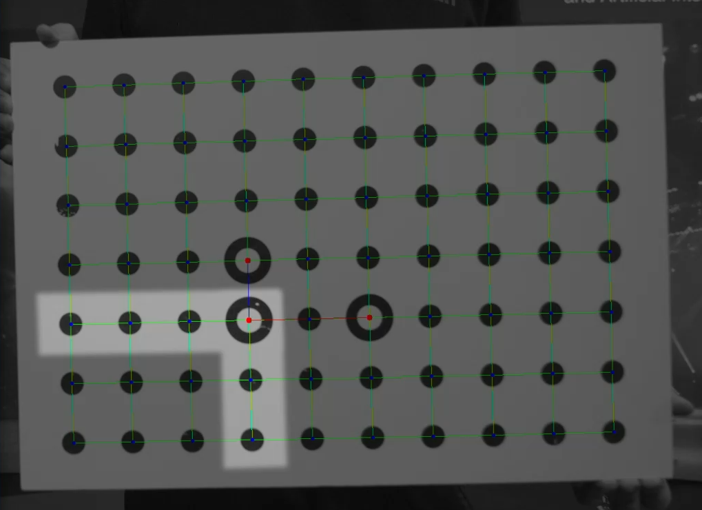
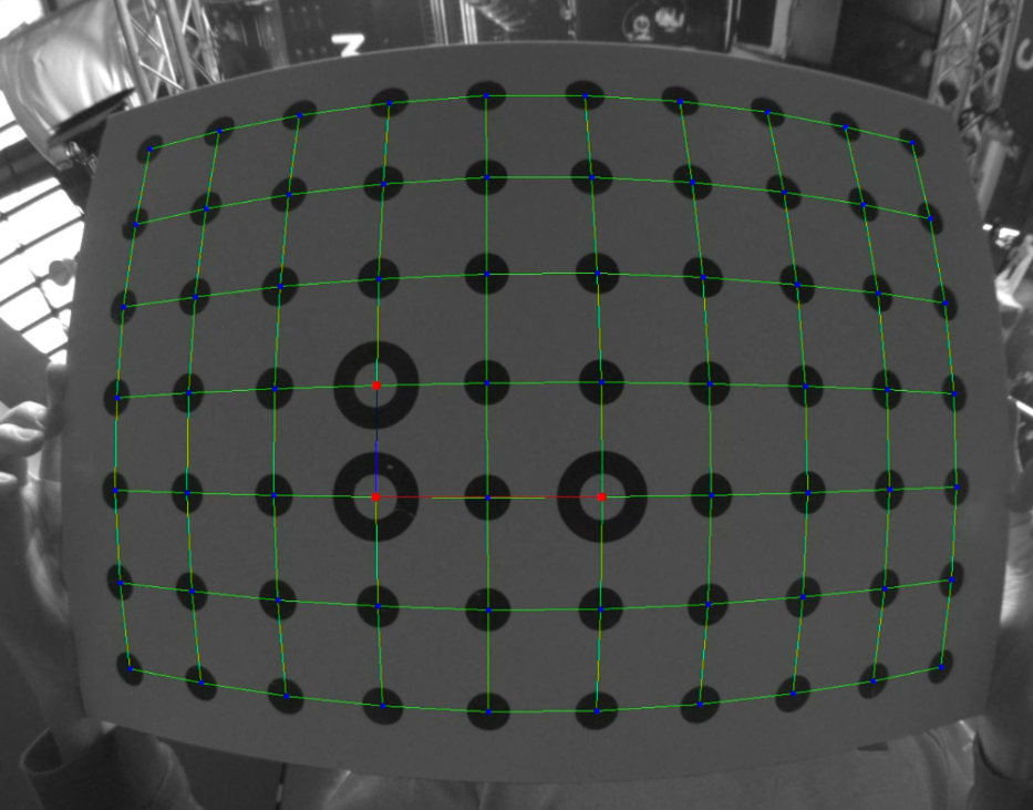
A fixed lens calibration file is created by sampling and analyzing the calibration pattern in the video. Multiple sample pictures of a hand-held calibration board are taken with the Fixed Lens Calibration software and are processed automatically.
2.1 Usage of FLC files
-
The Worker always needs the correct FLC file selected for the lens being used. That is whether you are using the Pixotope Sensor Unit camera in the Vision, Marker or GhosTrack version or any other camera for the Fly version. Feature points will be allocated differently on the camera chip depending on the distortion. In order to create and recognize a 3D point cloud that matches precisely with the reality this distortion has to be captured beforehand.
-
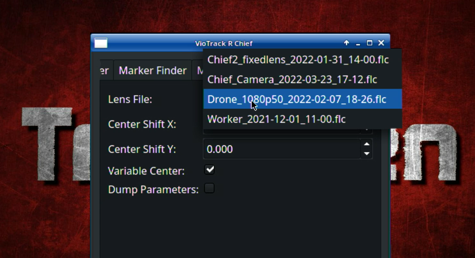
The Chief always needs a lens file selected in the Lens tab. The standard use case is that the ZLC provided by Pixotope for the zoom lens is selected. In case of using a prime lens, its FLC has to be selected. When using the Fly version, the same lens file as in the Worker has to be selected. The Chief transmits the lens parameters and if available the lens encoder values to the graphic engine.
-
For calibrating the offset between the Worker and the Chief camera an FLC file for each camera has to be selected. This means that even when using a zoom lens for the Chief an FLC for it needs to be created for the sole purpose of the offset calibration.
2.2 Factors of Influence
An FLC file describes the distortion of a lens with the exact settings of the influencing factors listed below at the moment the calibration is being done.
-
The focal length determines which area of the glass of a lens the light goes through. As such it has the main influence on the image distortion. That includes anything that has an influence on the focal length like extenders and converters.
-
Changing the focus setting of a lens can change the focal length more or less subtle. It has therefore an influence on the lens’ distortion. Besides that it can modify the arrangement of the simple lenses within a compound lens and by doing so change the distortion.
-
Depending on the camera, changing the video resolution may changes the part of the camera chip that is used for the image capturing. If that is the case, then another FLC has to be created before using this new video format. If the cameras sensor for example has a 4k sensor resolution, changing it to HD might cause the camera to crop the image, only using a smaller part of the sensor. The result is that these two video modes need two different FLC files. Some cameras also have a dedicated setting that determines the sensor size used.
-
Due to manufacturing tolerances no lens or camera mounting is perfect. This means that when reattaching the lens to the camera body it cannot be guaranteed that it will be on the exact same position thus altering properties such as Center Shift. Therefore it is recommended to create a new FLC file for the Chief camera, each time the lens has been removed and then reattached to the camera body.
-
Digital image stabilization that changes the used area of the image dynamically is not usable because such a mode makes it impossible to capture the lens distortion correctly. However, an image stabilization that crops the image by a fixed factor is possible to use. For using it the lens file has to be made with this image stabilizer being active. Please keep in mind that a digital image stabilization increases the video delay.
-
The apertures effect on the lens characteristics can be disregarded. However, changing the aperture can be necessary in two cases:
-
In case the surrounding environment is too dark for an ideal pattern recognition the aperture can be opened as long as the reduced depth of field is unproblematic.
-
In some cases, for example for telephoto lenses, the short depth of field makes the pattern recognition difficult. In these cases increasing the depth of field by closing the aperture can help. The resulting loss of light has to be considered, though.
-
It is necessary to create a new FLC for the same lens if any of points 1 to 5 from the list above changes permanently.
3 Creating an FLC file
3.1 Image Source
-
Start Fixed Lens Calibration.
-
Open the Settings and set the correct video source in the Camera tab.
For calibrating a Pixotope sensor camera choose either Spinnaker or Vimba depending on the model of the sensor camera. Vimba models have an ethernet port that is 90 degrees rotated to the side.
3. After changing the video source click on Change / Restart image source. The video should now be visible in the programs window.
3.2 Calibration Pattern
When using the Pixotope calibration board the default settings don’t need to be changed. Check chapter 4 when a customized pattern needs to be used.
3.2.1 Pattern recognition
Hold the calibration board in front of the lens to examine its visibility. Try to achieve the best possible pattern recognition:
-
Move camera and board to a generally bright area.
-
Change aperture, gain or shutter speed of the film camera if necessary.
-
In case the surrounding environment is too dark for an ideal pattern recognition the aperture can be opened as long as the reduced depth of field is unproblematic.
-
In some cases, for example for telephoto lenses, the short depth of field makes the pattern recognition difficult. In these cases increasing the depth of field by closing the aperture can help. The resulting loss of light has to be considered, though.
-
-
In case of a sensor camera change Exposure time, Gain and Gamma in the Camera tab if necessary.
In case the program has difficulties to recognize the pattern go to the Pattern tab and change the Image rendermode to Segmenter. This will display the binarized image. Adjust the Threshold value to try optimizing the pattern recognition. The default value is 116.
3.3 Calibration Process
Refer to the video tutorial for a visual representation of the process
1. Chief lens: It is recommended to set up zoom and focus to a setting to which it is easy to come back to with exact precision:
a. Set the focus(-ring) to the maximum value on the infinity side.
b. Zoom all the way out by turning the zoom ring to maximum.
This enables oneself to always set zoom and focus back to the exact setting with which the FLC was made.
2. Worker lens: make sure the focus and aperture positions are set and fixed and are adequate for the application.
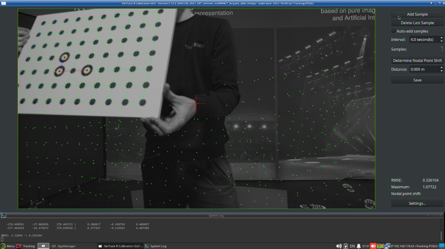
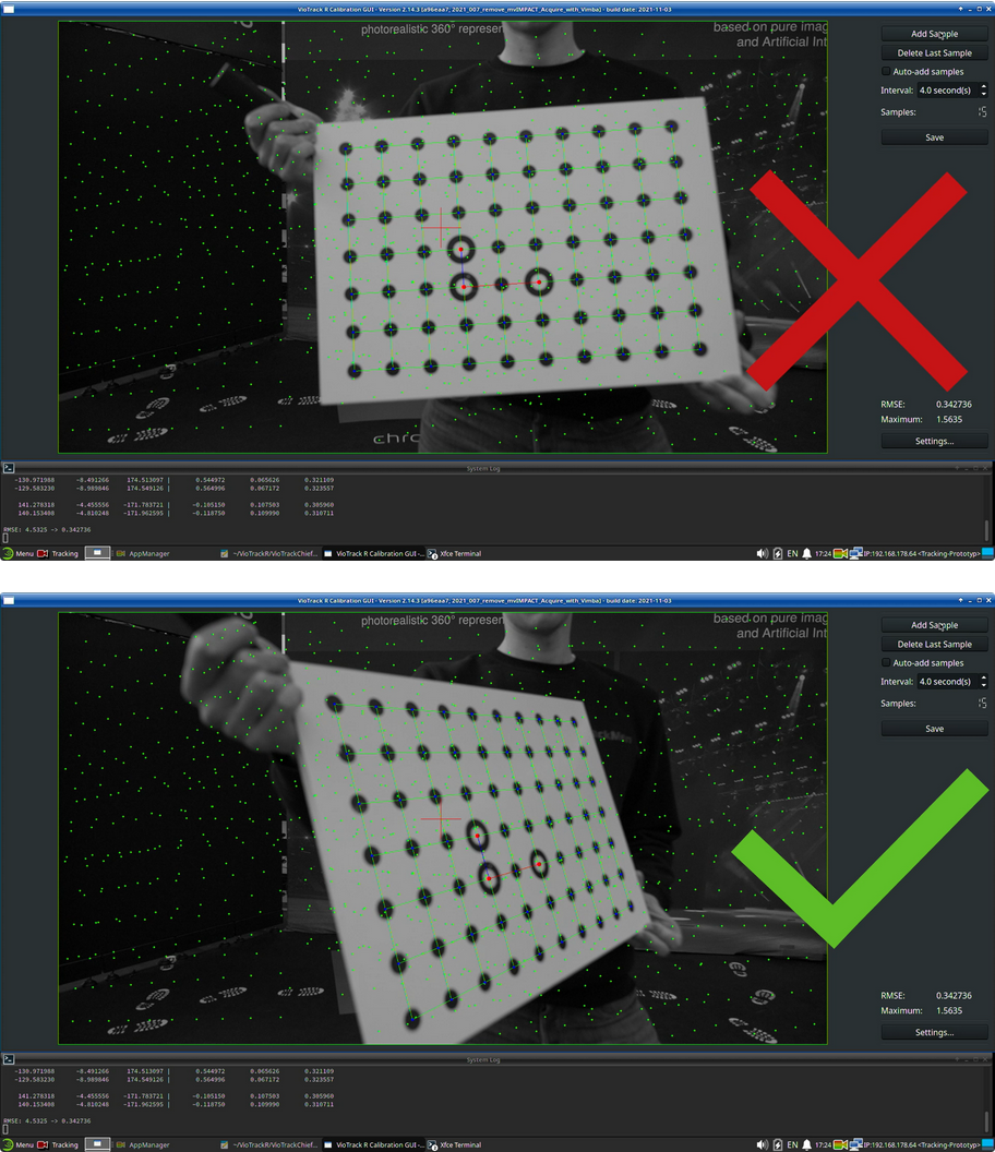
3. Click Add Sample to capture the lens distortion for the area of the image in which the pattern is recognized. Keep the following points in mind while adding samples:
a. The board should cover approximately 1/6th to 1/3rd of the image. Adjust the distance to the camera to achieve this.
b. The board can be hand held but must be held as still as possible.
c. Light reflections on the board should be avoided
d. Do not cover any dot with your fingers.
e. Always hold the board at an angle to the camera, meaning that the board is never parallel to the cameras sensor chip.
4. Keep adding samples in all areas of the image until the entire image is covered with green dots.
5. While adding samples make sure that the green line which indicates the theoretical image border includes the entire image and also the corners.
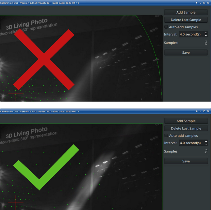
6. Make sure that the corners and edges of the image are also covered sufficiently with green dots.
7. Add one or two samples where the board is close to the camera and is covering more than half of the image.
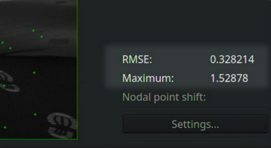
8. While adding samples make sure that the RMSE value stays below 1.0 and the Maximum value stays below 5.0. Values above these thresholds indicate that major errors occurred during the calibration process.
9. When at least 16 samples have been taken click Save.
10. Give the file a descriptive name, for example including the lens name. Date and time are appended automatically to the file name.
All lens files are stored in the /home/tracking/lenses folder.
4 Using a custom pattern
The settings which define the pattern can be found in the Pattern tab when activating the expert settings. When using the standard calibration board included in the shipment the default settings don’t need to be changed.
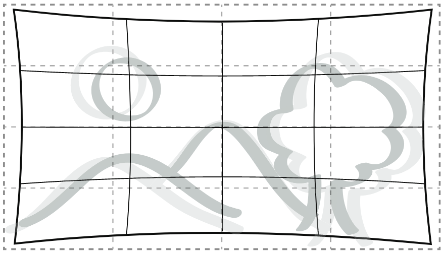
If printed on a flexible material the pattern needs to be fixed completely flat onto a perfectly plane board.
A pdf file with the single calibration target can be found here.
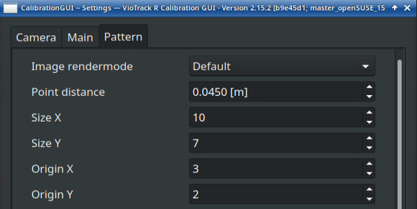
Point distance: The horizontal and vertical center-to-center distance between any pair of neighboring dots.
Size: The number of dots/circles in horizontal or vertical direction. X refers to the horizontal axis and Y to the vertical axis.
Origin: The position of the origin circle as indicated in Illustration 8. The position is the row of dots where the origin circle is located at in horizontal (X) and vertical (Y) direction. Row counting starting at 0, from left to right and from bottom to top.