1 Preface
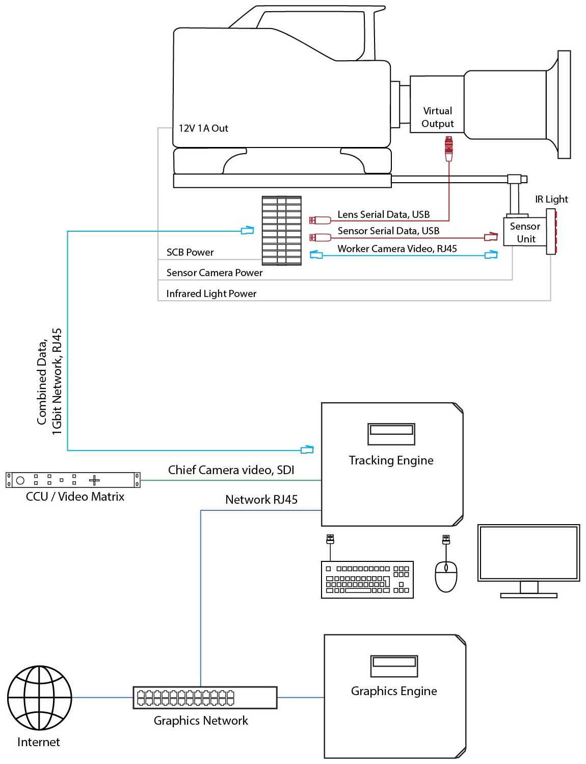
The Signal Collector Box (SCB) combines sensor camera video, motion sensor (IMU) data and lens encoder data into a single signal stream that is transmitted over one ethernet cable (min. Cat5e) to the tracking engine. Without the SCB, 3 separate ethernet cables are necessary.
2 Setup
2.1 Hardware Setup
-
A 3-way power cable provides power to the SCB, the sensor camera and the optional infrared ring light. Adapters work with 4-pin XLR, 4-pin Hirose or D-tap outputs from the camera body
-
The SCB is to be mounted onto the camera. A 15mm rod mount is included
-
Cables connecting the IMU and either the lens' virtual output or external lens encoders to the SCB are included
-
A short ethernet cable (min. Cat5e) to connect the sensor camera to the SCB is included
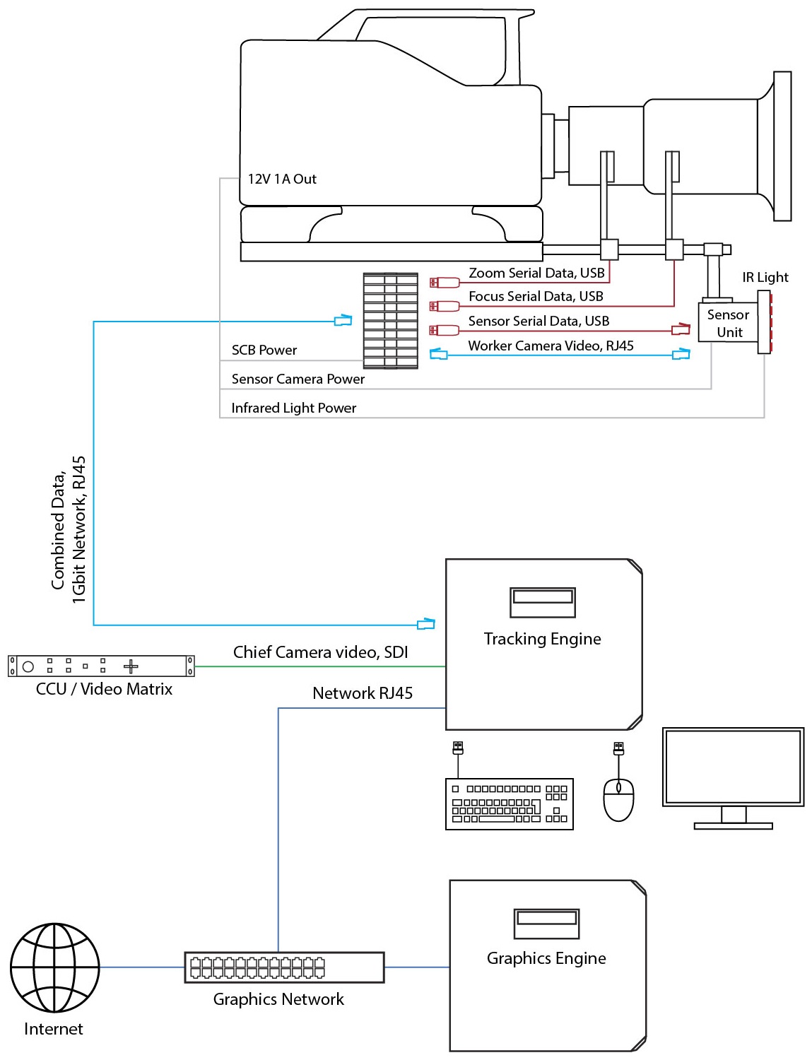
SCB with External Encoders
2.2 Software Setup
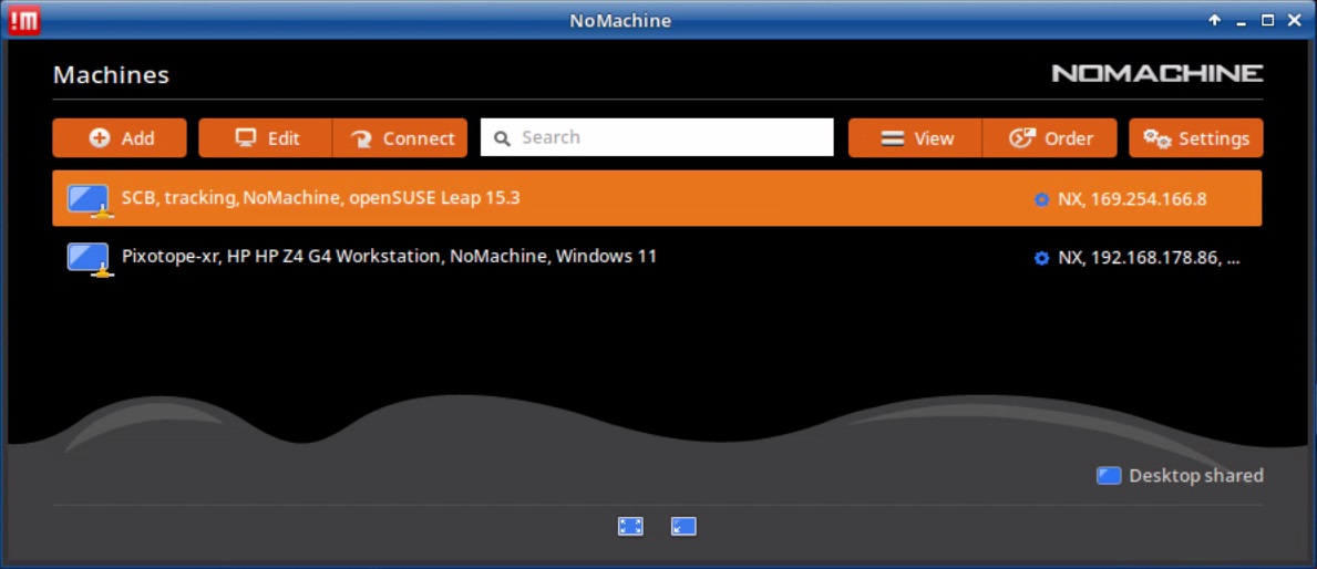
The SCB is a computer engine running a Pixotope Tracking Linux operating system and the Signal Collector software. Monitor, mouse and keyboard can be connected for access. However, the SCB can be accessed through the tracking engine via the remote control software NoMachine, which is preinstalled on every Pixotope Tracking operating system.
2.2.1 Network
-
Connect the ethernet cable from the SCB to the tracking engine and from the sensor camera to the SCB and power all devices
Both connections must be direct and exclusive. Both cables must be of high quality, shielded and capable to transmit at least 1 Gbit/s.
-
On the tracking engine set up the network connection as described in the operating system manual for your local network
For connecting to the SCB and for data transmission the tracking engine uses the link-local connection ZeroConf, which usually connects to the sensor camera when no SCB is used.
-
Connect to the SCB using the ZeroConf connection as described in chapter 6.2.1 of the operating system. The correct port needs to be selected in the ZeroConf connection
-
After the ZeroConf connection has been established, the SCB will appear in NoMachine.
-
Start a connection to the SCB
2.2.2 SCB Software
The Signal Collector software will run automatically when the SCB is powered. The SCB will also assign two network connections. ZeroConf connects to the sensor camera, eth0 connects to the tracking engine.
Keep in mind that ZeroConf describes two different things when using an SCB:
-
For the tracking engine ZeroConf is the connection to the SCB, transmitting video, data and remote control. eth1 is the network connection to the graphic engine
-
For the SCB ZeroConf is the connection to the sensor camera and eth1 is the connection to the tracking engine
-
Click on the Setup button in the Signal Collector window
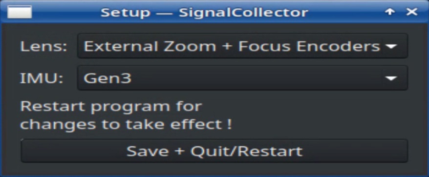
-
Choose the setup according to your application
-
Click Save + Quit/Restart
-
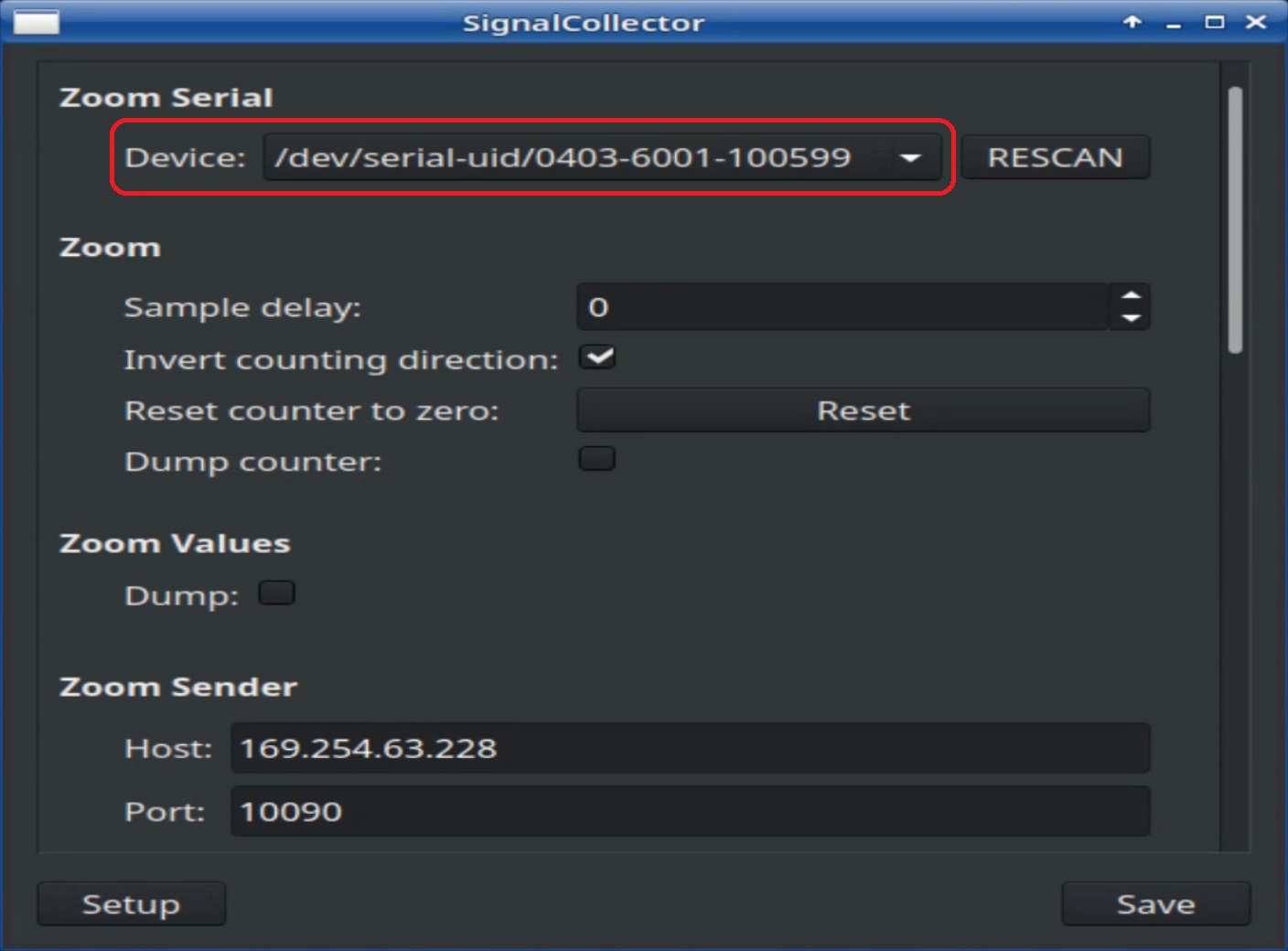
Connect one USB connector at a time and click on RESCAN to find out its Device ID
-
Connect all USB connectors and assign the correct IDs in the Device fields
-
Fixed lens: assign IMU adapter ID
-
External encoders: assign zoom, focus and IMU adapter IDs
-
Canon or Fujinon lens: assign Canon or Fujinon adapter ID and IMU adapter ID
-
-
Save and restart the software by clicking on the X in the upper right corner
-
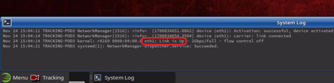
Test all connections by activating the respective Dump and controlling the System Log output
The Host and Port fields under each section will be set automatically by the software after each software start. Do not change them!
2.2.3 Chief
-
Start the Chief process on the tracking engine
-
Click on the Setup button
-
Choose the entire Chief setup as if no SCB is being used
For this initial setup, choose the same settings for IMU and lens as in the SCB software Setup (action point 1. in the previous chapter).
-
Click Save + Quit/Restart
-
Click on the Setup button again
-
In the Lens and IMU fields select the corresponding Signal Collector (SCB) settings
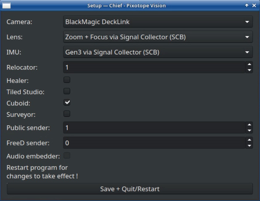
-
Click Save + Quit/Restart
-
Check if the inputs are working by dumping lens and IMU values from the Chief window and controlling the output in the System Log window
2.2.4 Worker
-
Start the Worker process on the tracking engine
-
Open the Settings and go to the Camera tab
-
Select the Interface type and click on Change image source
3 Software update
The Signal Collector software will come preinstalled on the box. In case it is necessary, the software can be updated with the internet or with a USB stick, similar to chapter 4 in the operating system manual.
3.1 Updating software from the internet
Monitor, mouse and keyboard can be connected to the SCB for convenience. Otherwise it is possible to disconnect the Worker camera cable and replace it with a cable that provides an internet connection.
-
Unplug the ethernet cable to the sensor camera from the SCB
-
Connect an ethernet cable with an internet connection to the empty ethernet port of the SCB. When plugging in the cable, the SCB will automatically connect to this new connection as eth0
-
Disconnect from this new connection manually
-
Connect to eth0 manually
The eth0 connection must be configured to use DHCP.
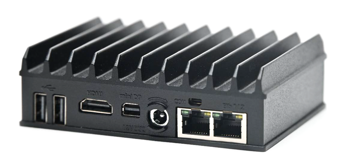
4 Specifications
|
Dimensions |
112 x 84 x 34 mm |
USB |
2 x USB 3.0
|
|---|---|---|---|
|
Weight |
380 g |
LAN |
2 x GbE ports |
|
Cooling |
Fanless convection cooling through the housing, no vents |
Monitor |
1 x HDMI and
|
|
Mounting |
Mounting for standard 1/4-20 UNC thread (camera thread) and universal clamp included |
Input Voltage |
9V – 20V |
|
|
|
Power Consumption |
Powered via camera body or external power supply.
|