This panel is available when using an XR license
When doing XR, it is essential to perfectly align the physical LED wall with its virtual representation (XR walls). This is the baseline for projecting graphics onto them and achieving a believable parallax and XR/AR-set extension illusion.
Historically this has been done manually measuring the size and location of the LED wall. Having a LIDAR scan of the geometry helped. This process is obviously quite time consuming and hard, but can still be seen as a fallback solution.
Learn more about Manual XR alignment
Automatic alignment
Requires Pixotope Tracking
Together with Pixotope Tracking we provide an automatic way of alignment, where image processing is used to scan the actual position and orientation of each individual LED panel.
This is a 3-step process
-
Pixotope Tracking generates a marker pattern which is displayed on the LED walls
-
Pixotope Tracking generates Digital Twin data based on the location of the LED walls
-
Pixotope Graphics creates the Digital Twin and
Generate Digital Twin data using Pixotope Tracking
Prerequisite: The Pixotope Tracking sensor camera needs to be calibrated. Meaning that a lens file has to be made.
Generate a marker pattern for each LED body*
-
Open the Marker Pattern Generator
-
Create a marker pattern that covers all parts of the LED XR stage
-
You can create multiple patterns by dividing parts of the XR stage into bodies*. Each wall, floor or ceiling segment can be a new body
-
-
Collect and enter the needed data
-
The Marker Pattern Generator automatically creates the pattern in a way that displays one marker per LED panel. Be aware that the markers need to be visible from different distances and that there needs to be space between them to make sure the software can differentiate between them
-
Consider using a Checkered pattern. The Digital twin will interpolate the information for the panels without markers
-
-
In the Global Settings you can set the origin, orientation and scale of the virtual world
-
This information will be saved in the config file. The position and orientation of each panel is then related to this coordinate system. However you can set this also later on in the Marker Calibration program
-
-
Export the pattern as a PNG image and display it onto the LED panels
-
The blue squares in the corners indicate if the pattern is displayed correctly
-
-
Save the configuration file (usually "VioStudio.cfg") using the “File” menu in the top left corner
The same marker pattern can be used for calibrating the offset between the sensor camera and the film camera as well as for determining the optical parameters of your zoom lens. Also the AutoInit function can use the same markers. Please see the Pixotope Tracking documentation for more details.
Generate the digital twin data and send it to Pixotope Graphics
-
Start "VioTrack R Marker Calibration" (or "GhostTrack Marker Calibration")
-
Open the Settings and activate “Show expert settings”
-
Configure to use the right "VioStudio.cfg" and lens file
-
-
Go to the DataHub tab and enter the Pixotope Data Hub IP address which can be found in Director > Status panel
-
Make sure that the program sees and identifies as many markers as possible also by finding the ideal Threshold value in the Marker tab
-
Click Save and restart the program
-
Perform a reconstruction including all markers on the LED panels from different angles and positions, including being very close to the panels
-
Open the Marker Calibration menu
-
If needed, determine the origin, orientation and scale
-
Click "Process Markers"
-
Check if theoretical position of markers (in red) match actual markers and if the coordinate system is correct
-
-
The Digital Twin data is being sent to the Pixotope Store in the moment when the processing of the markers is finished
* An LED body is one continuous LED surface. A curved wall with a floor would be 2 separate bodies.
The Digital Twin data can later be used to fine tune the precision of the tracking. Please see the Pixotope Tracking documentation for more details.
Create the Digital Twin
Create the Digital Twin
-
Open your XR level in the Pixotope Editor
-
Add the Digital Twin XR actor to your scene
-
The actor gets automatically placed as a child underneath the camera root
-
-
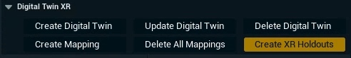
Click the "Create Digital Twin" button on the Digital Twin XR actor
-
For each LED body it creates an XR wall actor for every single LED tile
-
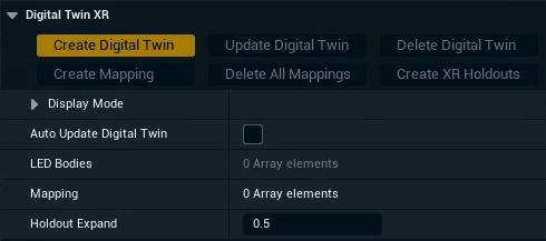
Update or Delete the Digital Twin
If the digital twin data has been updated:
-
Click "Update Digital Twin"
This will recreate/reposition the XR walls.
If the pixel data of the LED wall has changed, existing mappings have to be recreated.
Enable Auto Update Digital Twin to continuously read the Digital Twin Data sent from Pixotope Tracking. This is mainly used for testing.
To completely start over:
-
Click "Delete Digital Twin”
This will reset the Digital Twin XR actor and delete all related XR walls.
The digital twin data which was sent to Pixotope Graphics is NOT deleted.
Create mappings of LED Bodies
A mapping defines which XR walls/which parts of your LED wall are being outputted together. If your LED wall resolution is larger than your output resolution, you will need
-
Multiple render machines
-
OR Multiple outputs
NOTE: This option needs an "Additional output" license -
OR Select “Scale to Fit” under Graphics Scale while creating the Mapping
NOTE: This will not use the full resolution potential of your wall
-
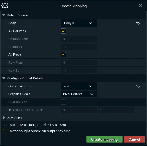
Click "Create Mapping"
-
Select the LED Body you are creating a mapping for
-
Specify how many columns and rows it should cover
-
To only select a specific range, uncheck "All Columns" and enter From and To values
-
Columns and Rows start with
0. You can use-1to indicate the maximum value.
-
-
NOTE: The pixel size available vs needed for the selected range can be seen on the bottom of the dialog after you have selected “Output size from”
-
-
Select a routed output to specify the mapping size
-
Select the graphics scale
-
Use the Scaled option only for testing as it reduces the picture quality
-
-
Click "Create mapping"
Repeat this step to create more mappings, if your LED wall resolution is larger than your output resolution.
Select output machines
In a multi-machine setup you can specify which mapping should be rendered by which machine.
-
Expand the details of a specific mapping
-
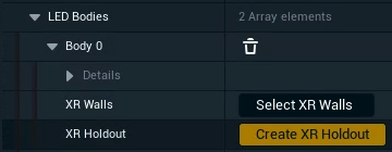
Click on "Select XR walls"
-
The detail view switches to the XR walls related to this mapping
-
-
Select the Output channel, if you have multiple outputs available
-
Enter the machine name which should
Identify your mappings
To check that your mappings have been setup and output correctly.
-
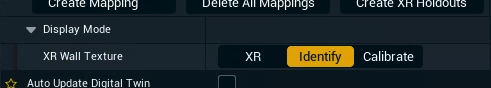
Expand Display Mode
-
Choose "Identify" for the XR Wall Texture
Check your calibration using an AR machine
To check how accurate your digital twin is:
-
Expand Display Mode
-
Choose "Calibrate" for the XR Wall Texture
On all XR machines: XR walls are output with red edges.
On the AR machine: XR walls are output with green edges.
When the wall is perfectly calibrated, the lines should overlap and appear yellow.
Create XR holdout
-
Click "Create XR Holdouts" to create translucent holdouts for all LED Bodies
To create a holdout for a specific body, click the "Create XR Holdout" button there.
Optionally: Change the Holdout Expand value before creating the holdout to slightly expand the holdout.
XR holdouts are not rendered when XR is enabled
Learn more about how to Set up a virtual set extension with translucent holdouts