For XR productions where the set should be extended beyond the XR walls (LED screens) the following setup is needed:
-
A render machine for the XR wall
-
A render machine for the virtual set extension
-
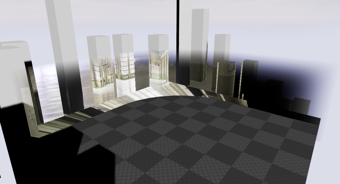
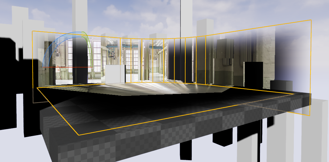
Translucent holdouts are used to make the transition to the XR wall seamless
-
The virtual set extension can be thought of as an AR scene with a hole punched through to the raw camera video in the area occupied by the physical LED screens.
Learn how to Calibrate color matching between the LED walls and the AR set extension.
Learn more about how to Sync an XR wall with a virtual set extension
Set up a combined level
The settings and the content displayed on the XR machines compared to the one on the set extension machine are only slightly different.
|
|
XR machines |
Set extension machine |
|---|---|---|
|
Mode |
XR enabled |
AR enabled |
|
Content |
Same for all machines
|
|
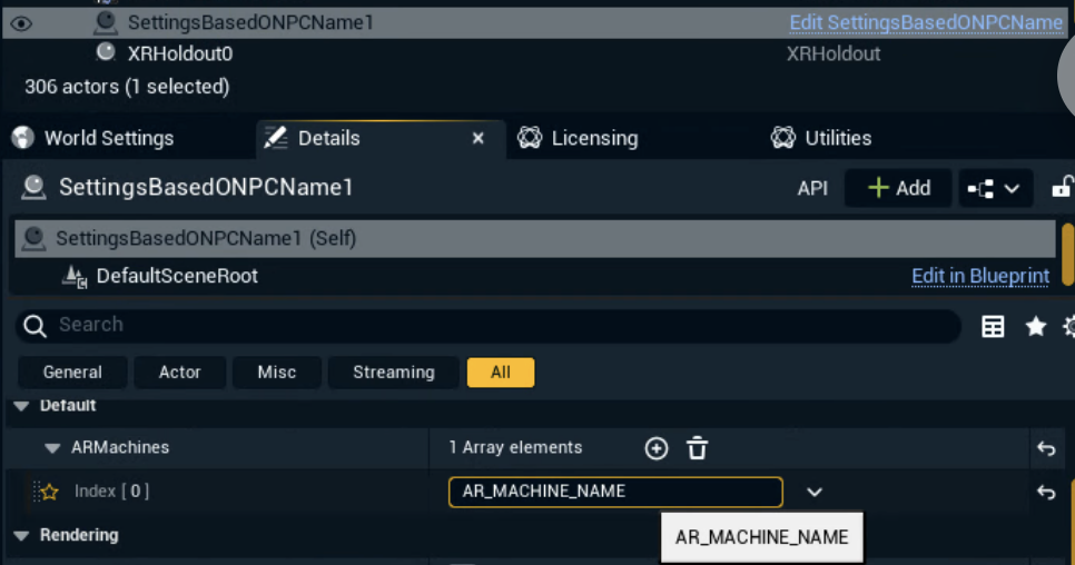
To not have to create a separate level where XR/AR are enabled/disabled you can use a blueprint which switches the mode based on the machine name.
-
Copy the
SettingsBasedOnPCNameblueprint into your project-
Can be found in the LVL_PixotopeXRSample level of the preinstalled Calibration project
-
-
Drag and drop into your level
-
Enter the machine name of the Set extension machine on the
ARMachinesarray
Use the windows machine name, not the display name defined in Director!
Set up level streaming for more separation
For more separation you can use level streaming instead.
Set up level streaming
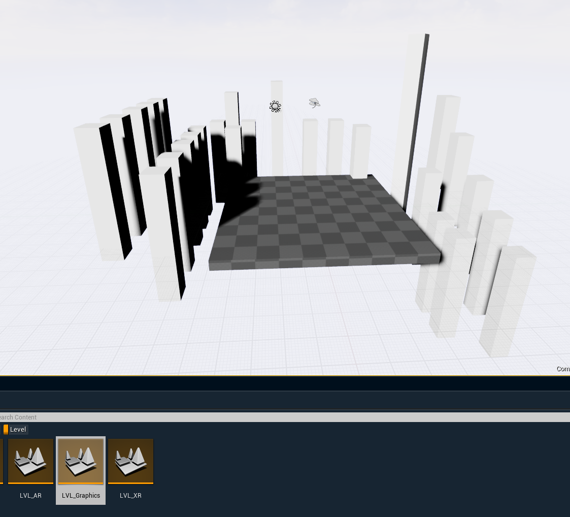
The levels for the XR wall and the virtual set extension will have the same graphics content but need different setups. To avoid copying the graphics content between the 2 levels, we suggest the use of level streaming. In this setup the graphics content is kept in a separate level and streamed into the XR wall and the XR extension level, making sure the content of the 2 levels are always in sync.
-
Graphics level
-
Contains no Pixotope setup
-
-
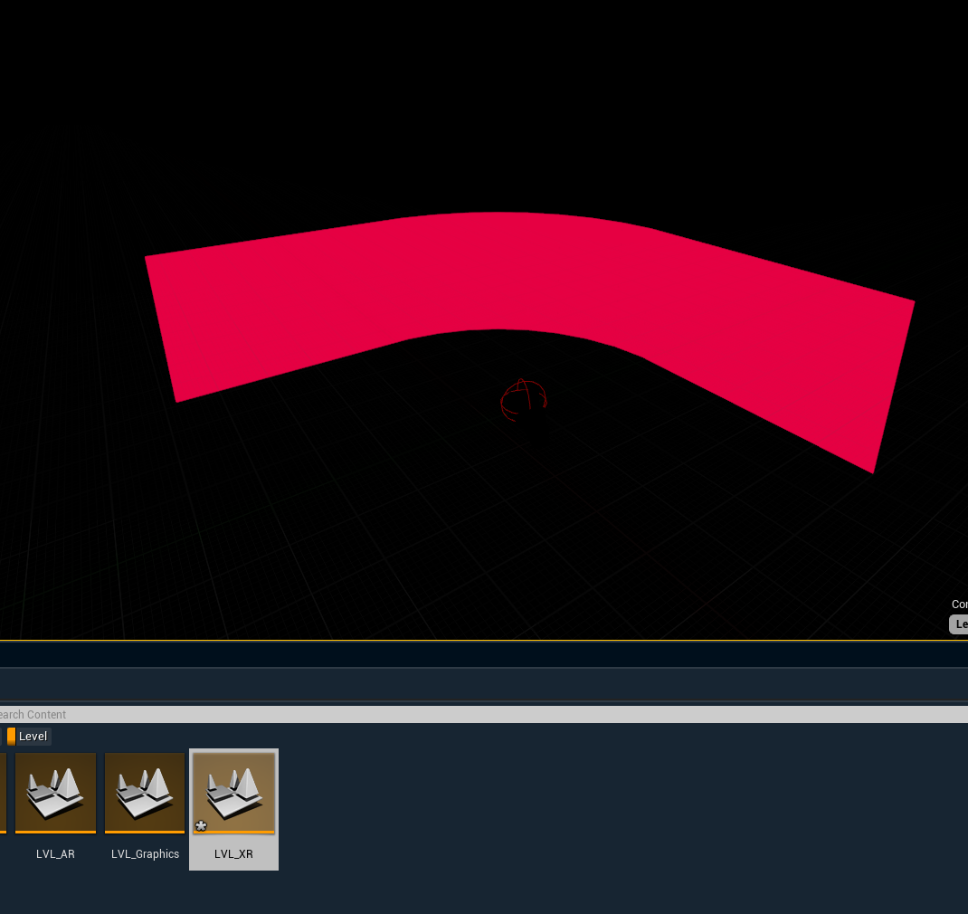
XR level
-
Contains the XR wall(s)
-
Graphics level is added as a streaming level
-
-
XR extension level
-
Contains the translucent holdouts
-
Graphics level is added as a streaming level
-
-
Create the graphics level
-
Create the XR level
-
for preparing an XR level with XR walls check out Setting up an XR level (virtual window)
-
-
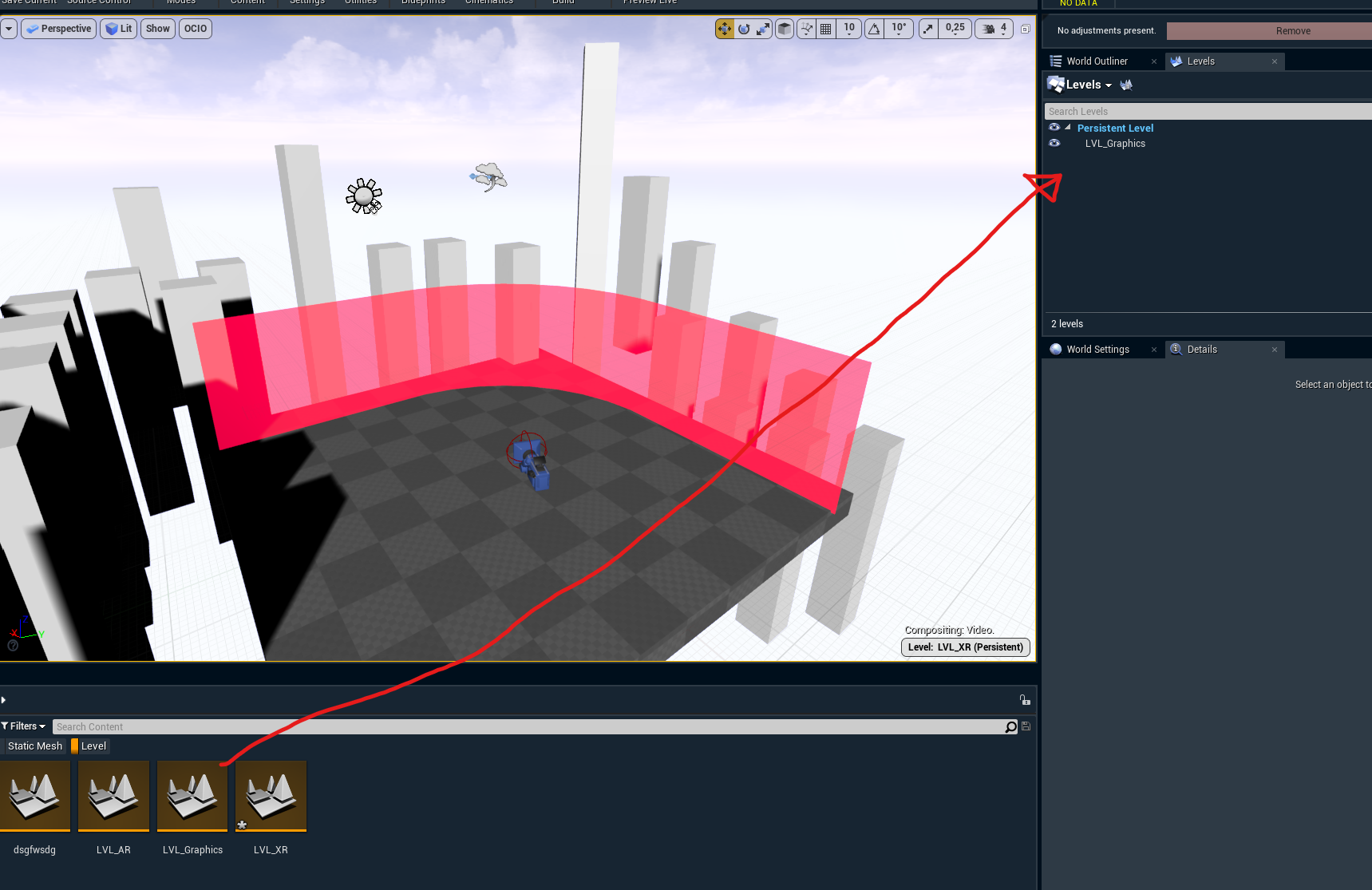
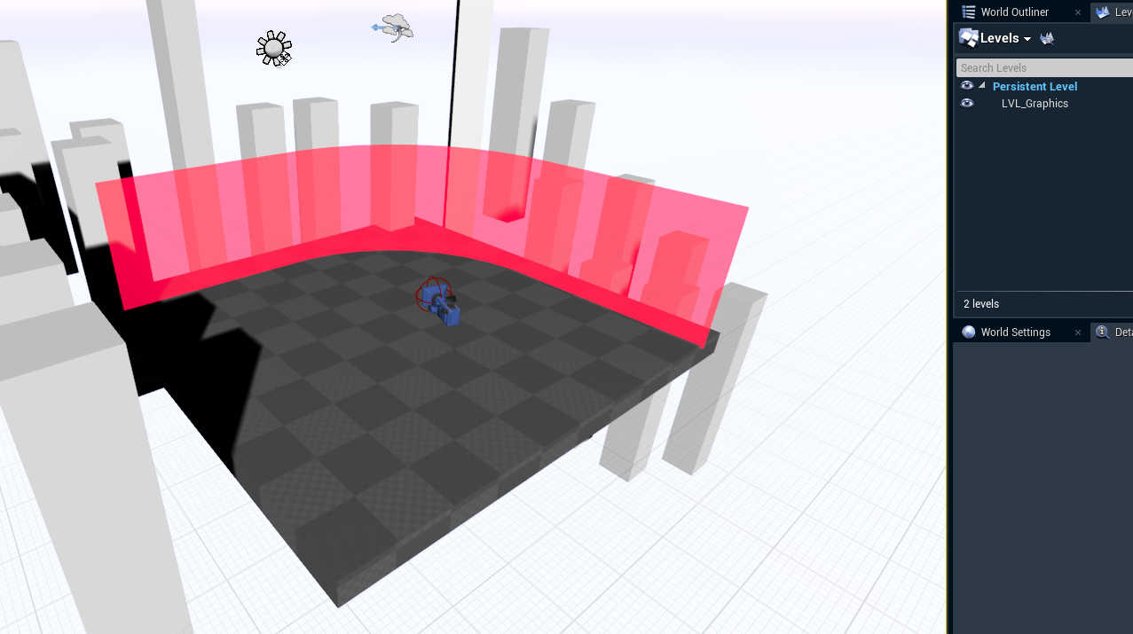
Add the Graphics level as a sublevel
-
Open the "Levels" window by clicking on Menu → Window → Levels
-
Drag the Graphics level into the "Levels" window over "Persistent Level"
-
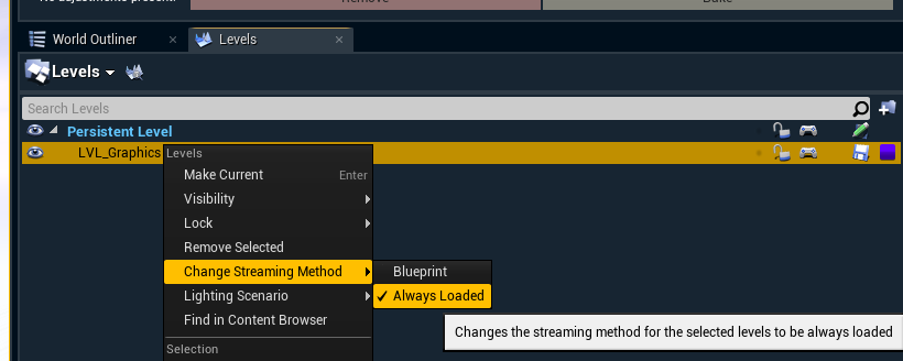
Make it persist by right clicking the Graphics level → Change Streaming Method → Always Loaded
-
-
Repeat step 2 and 3 for the XR extension level
Now the XR and the XR extension level maintain a single/shared graphics level for all the creative content.
Set up the translucent holdouts
-
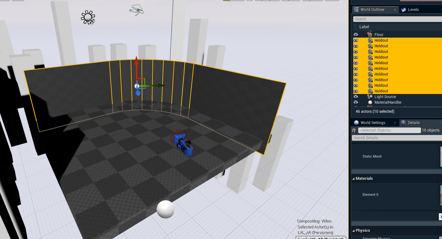
Create the geometry for the holdouts to perfectly align with the XR wall(s) in your XR level
-
XR wall example
-
Respective holdout geometry
-
-
Select all holdout actors
-
Click on "Convert Actors to Translucent Holdout" via right click in the Pixotope section
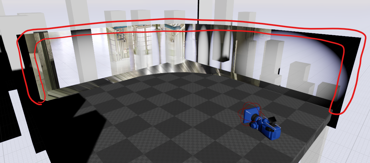
NOTE: This sets the desired stencil value required by Pixotope's compositing pipeline and applies a default mask material with a radial gradient.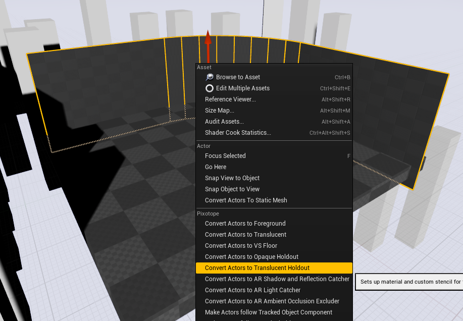
Result with the default material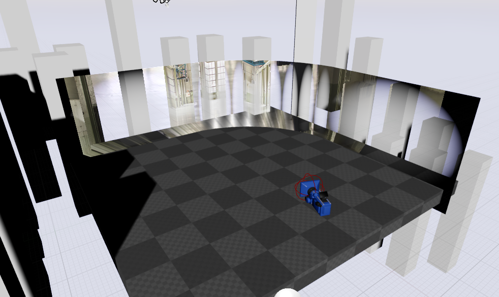
-
Replace the default material if needed
You can make your mask material any way you want.
For complex geometry, you could manually paint a custom mask and use that for your material opacity.
Or you could create a custom shader with procedural control.
In this example we create a custom shader with procedural control
-
Identify the areas you want to fade out
-
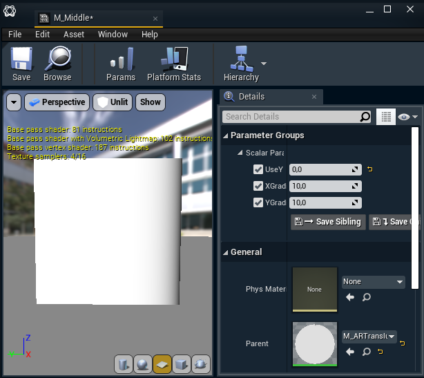
the curved section in the middle only needs a vertical fade
-
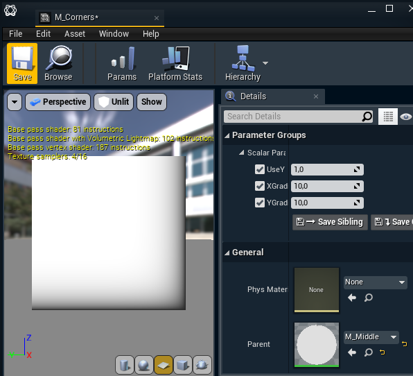
the two corner planes need to fade out both vertically, as well as horizontally
-
-
Make a copy of the AR_TranslucentHoldout material or a new material from scratch.
-
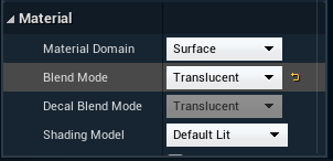
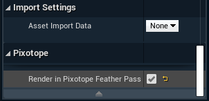
In the Details panel change the Blend mode of this material to "Translucent" and enable "Render in Pixotope Feather Pass" if this is not already done.
-
To do what we want, the material should look like this. We are using the linear gradient shader as a base and building on it to create both mid section holdouts, and corner segments.
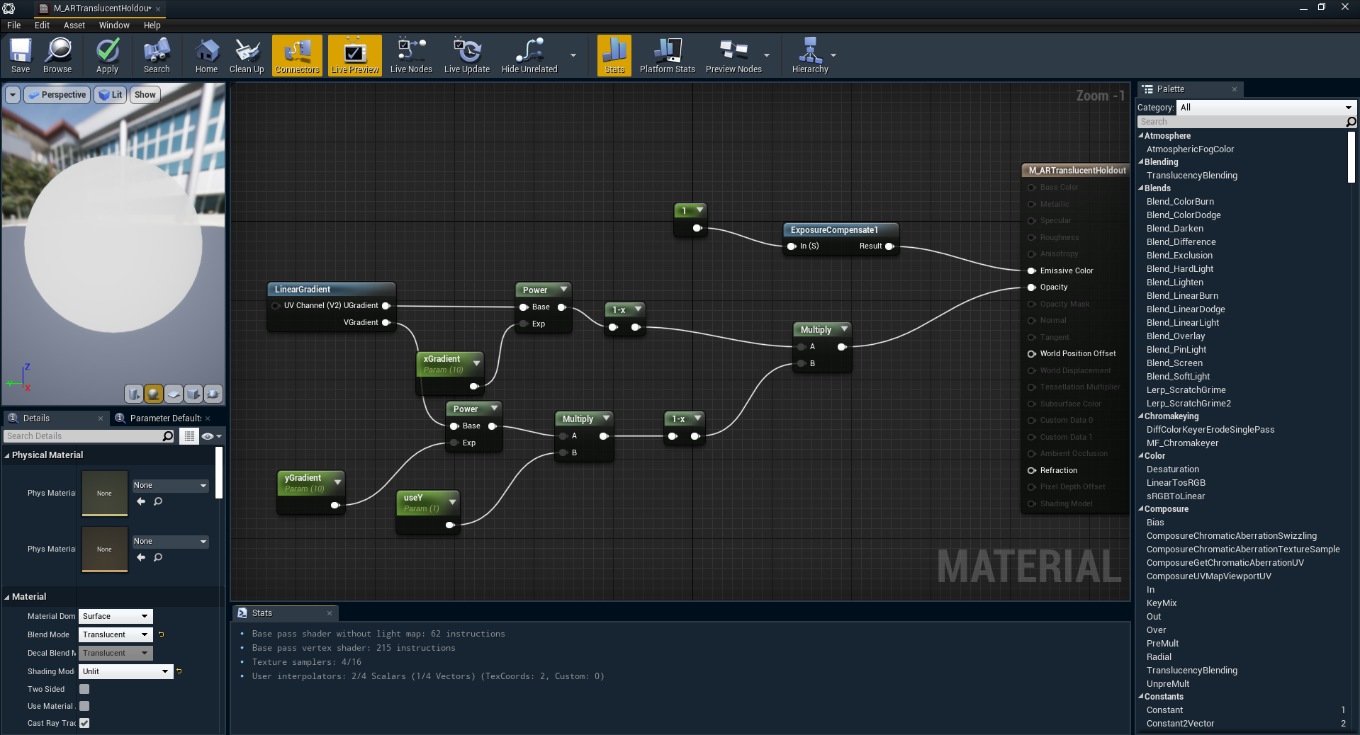
-
Crate two material instances - one for the mid sections, another for the corners
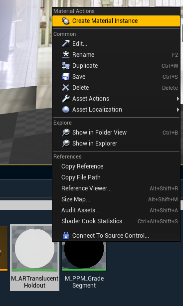
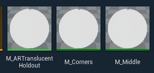
-
Assign the materials to the respective holdout sections
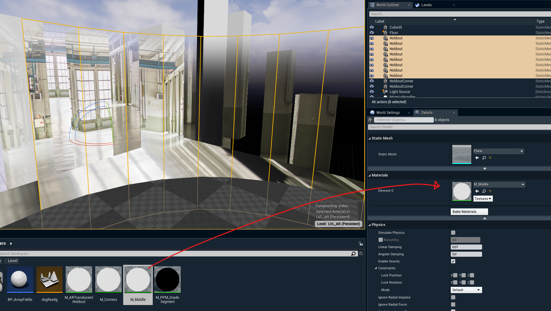
-
-
At this point, you should be seeing a perfect gradient all around the holdouts, and we are done with our setup