Pixotope Graphics supports SMPTE 2110 uncompressed video over IP using the Matrox DSX family of IP/Video cards.
Learn more about SMPTE 2110 in Pixotope Graphics
Prerequisites
License
A ST2110 Matrox addon/license is needed for
-
SMPTE 2110 input and output using a Matrox card
Drivers
-
Make sure the Matrox driver and SDK version installed is the one indicated here: System requirements - Video cards IP
-
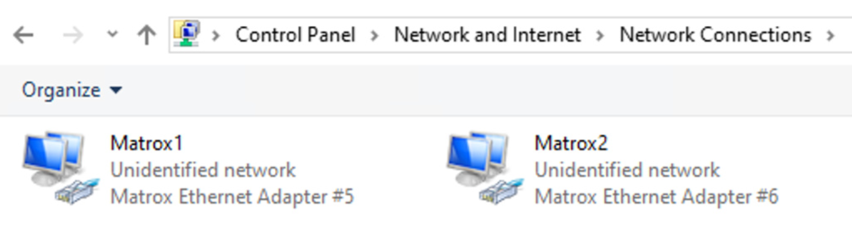
Make sure the card’s interfaces show up in the list of Network adapters in Windows settings. Example of a Matrox DSX LE5 D25 with dual interface
Network architecture and connection diagrams
The following diagrams present the most common network architectures and their connectivity using Matrox Dual IP cards (e.g. DSX LE5 D25).
Single and redundant network architecture
Single network architecture
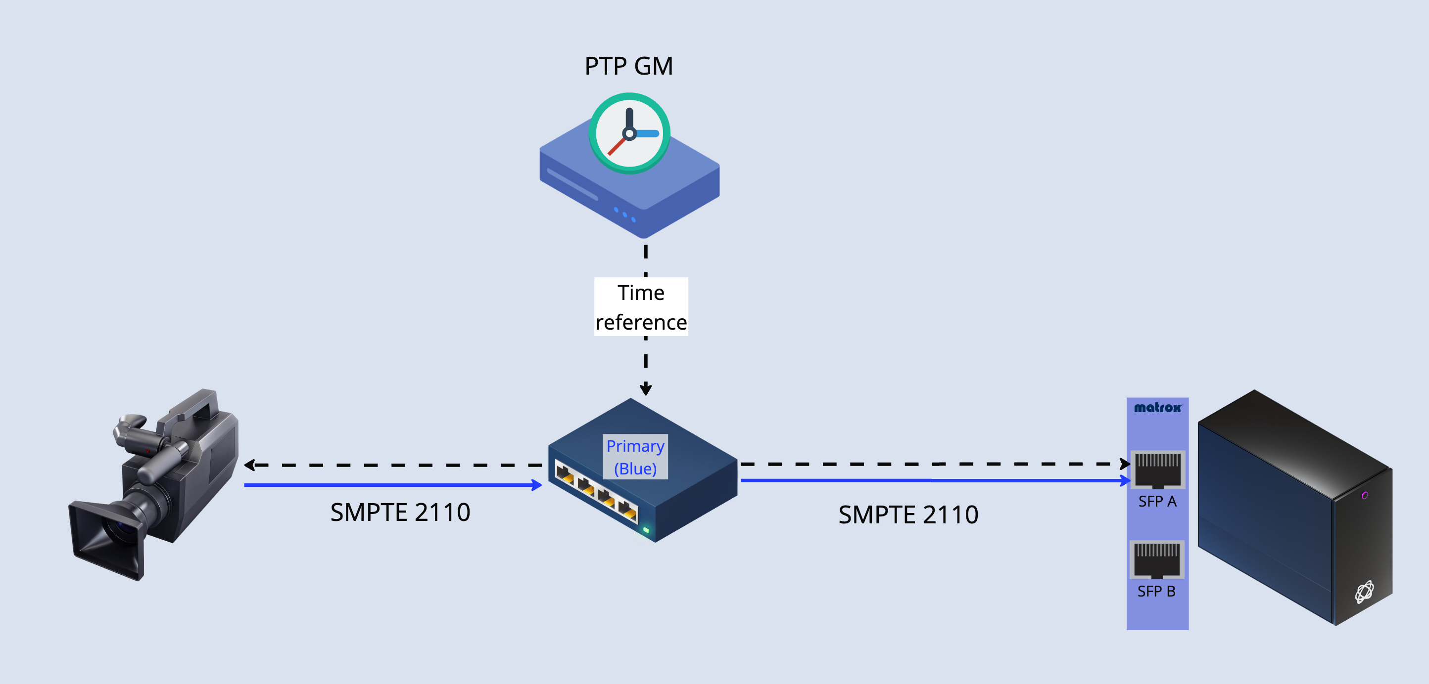
Example network configuration
-
SFP A
-
Media: 10.10.5.2
-
PTP (Virtual Interface): 10.10.5.3
-
Gateway: 10.10.5.1
-
Netmask: 255.255.255.0
-
Redundant network architecture - 1x PTP GM
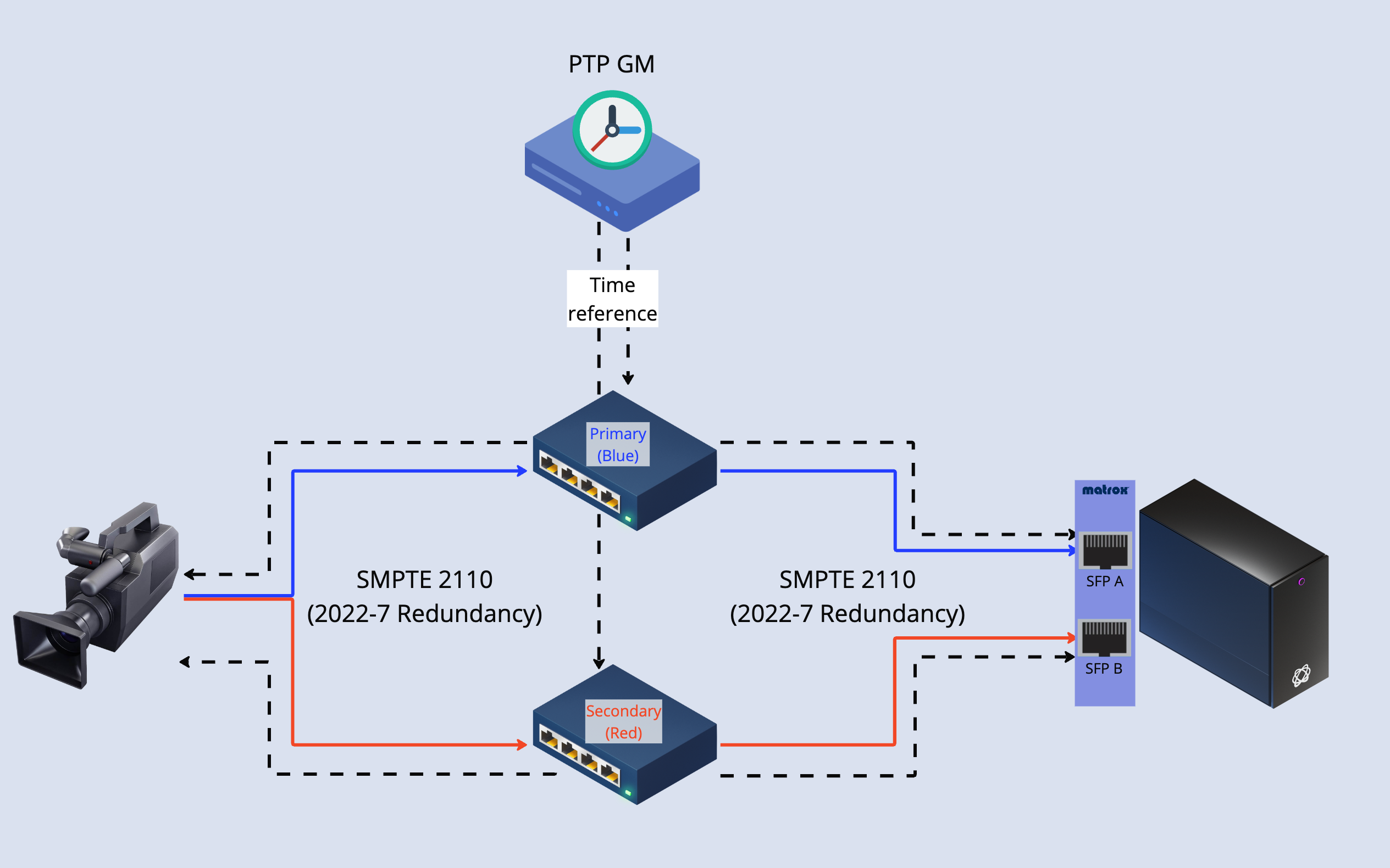
Example network configuration
-
SFP A
-
Media: 10.10.5.2
-
PTP (Virtual Interface): 10.10.5.3
-
Netmask: 255.255.255.0
-
Gateway: 10.10.5.1
-
-
SFP B
-
Media: 10.10.6.2
-
PTP (Virtual Interface): 10.10.6.3
-
Netmask: 255.255.255.0
-
Gateway: 10.10.6.1
-
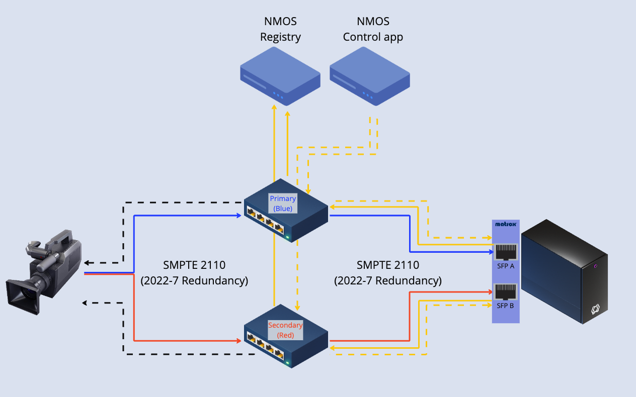
Redundant network architecture - 2x PTP GMs

Note 1: the second port is reserved for network redundancy (SMPTE 2022-7). In the case of the Quad IP card (Matrox DSX LE5 Q25), the second and the forth port will be reserved for redundancy, while the first and the third will be used for main I/O.
Note 2: For the Redundant Architecture with 2x PTP GMs, it is the responsibility of the network admin (external to Pixotope) to ensure that both PTP GMs are kept in sync.
Configure network interfaces for PTP and media
For each port (physical interface), the network needs two reserved static IP addresses in the same subnet:
-
PTP (virtual interface)
-
Media (2110)
For an example configuration see the Network architecture and connection diagrams above.
Configure PTP IP addresses
This is done through Pixotope Director > Machine Settings
Learn more about how to Configure Precision Time Protocol - PTP (2110)
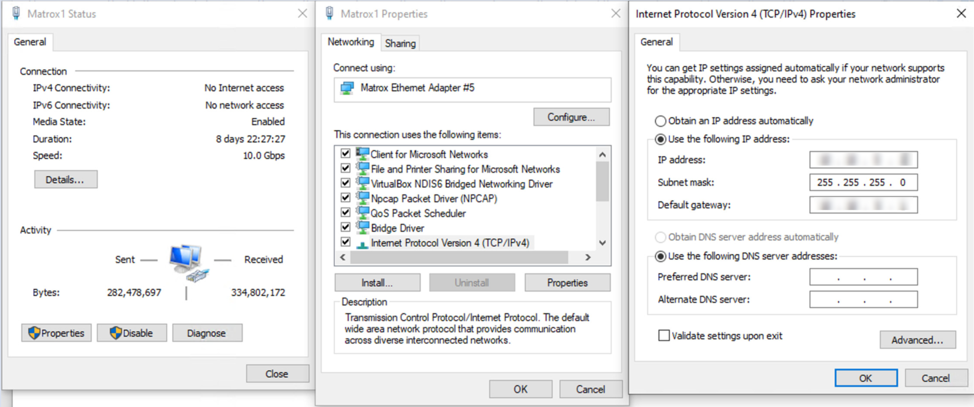
Configure media (2110) IP addresses
-
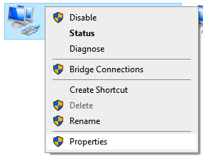
Right click the network adapter and click "Properties"
-
In the Windows network configuration enter
-
IP address
-
Subnet mask
-
Default gateway
-
Configure PTP
SMPTE 2110 requires a functioning PTP configuration.
Learn more about how to Configure Precision Time Protocol - PTP (2110)
Configure routing
-
Go to SETUP > Configure > Routing
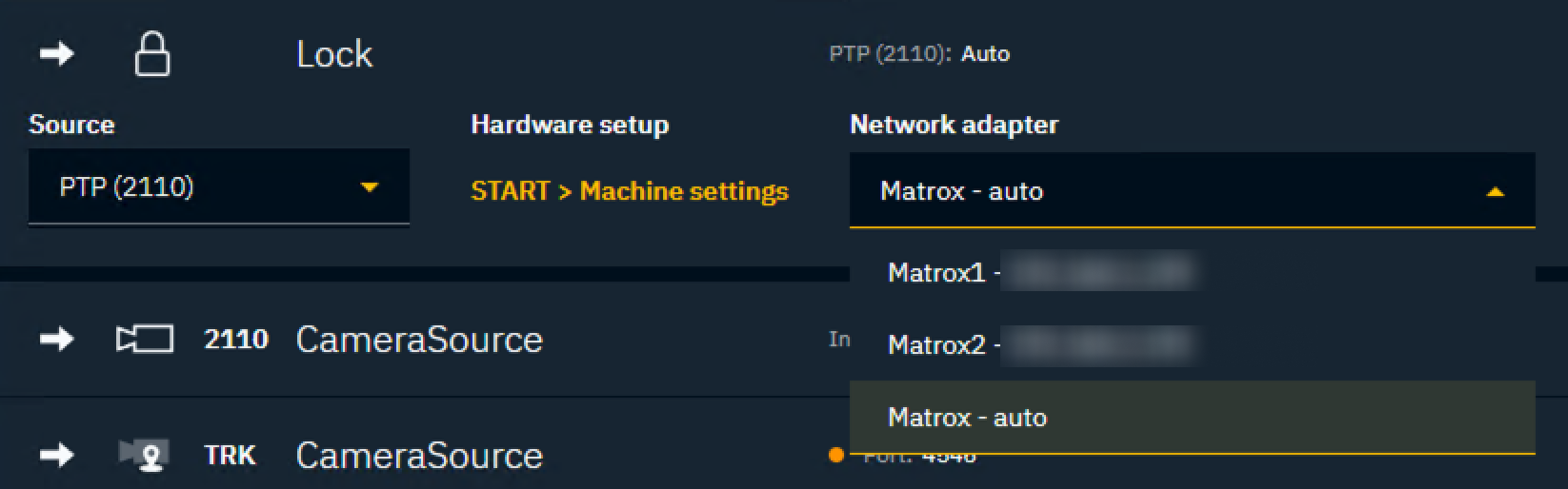
Configure lock
-
Set the Source to PTP (2110) in the Lock row
-
If not already done check the PTP (2110) configuration explained above
-
-
Optionally, change the Network adapter
-
The default and recommended selection is Matrox (auto) which will let the Matrox card select the source of PTP
-
In a redundant network architecture it selects the most reliable interface
-
In a single network architecture, it will default to the first port
-
Only select a specific network adapter if you want to force that PTP only comes through it, and prevent an automatic selection
-
Add inputs and outputs
-
Add Camera system or Media input the same way you would do for any other type of input
Learn more about how to Configure routing
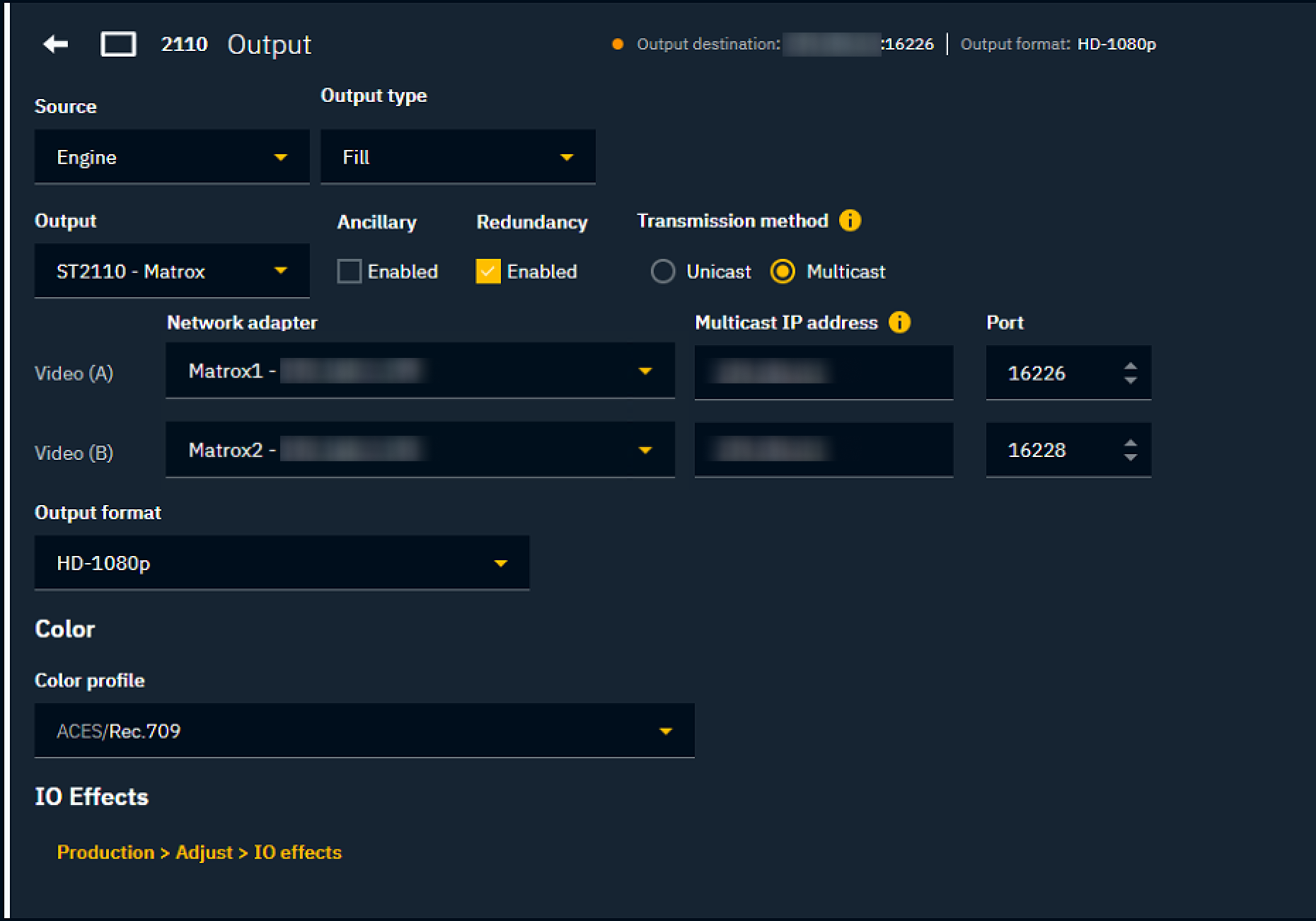
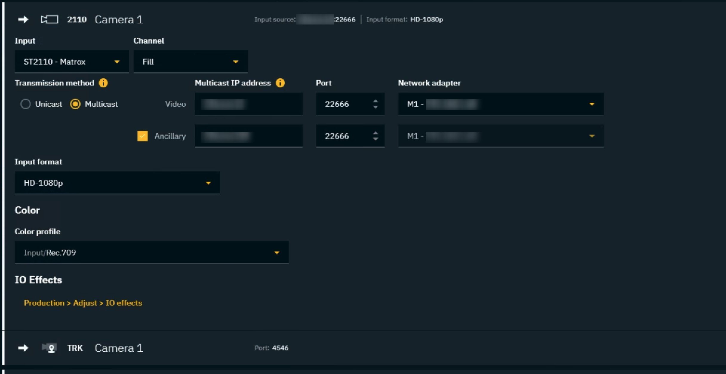
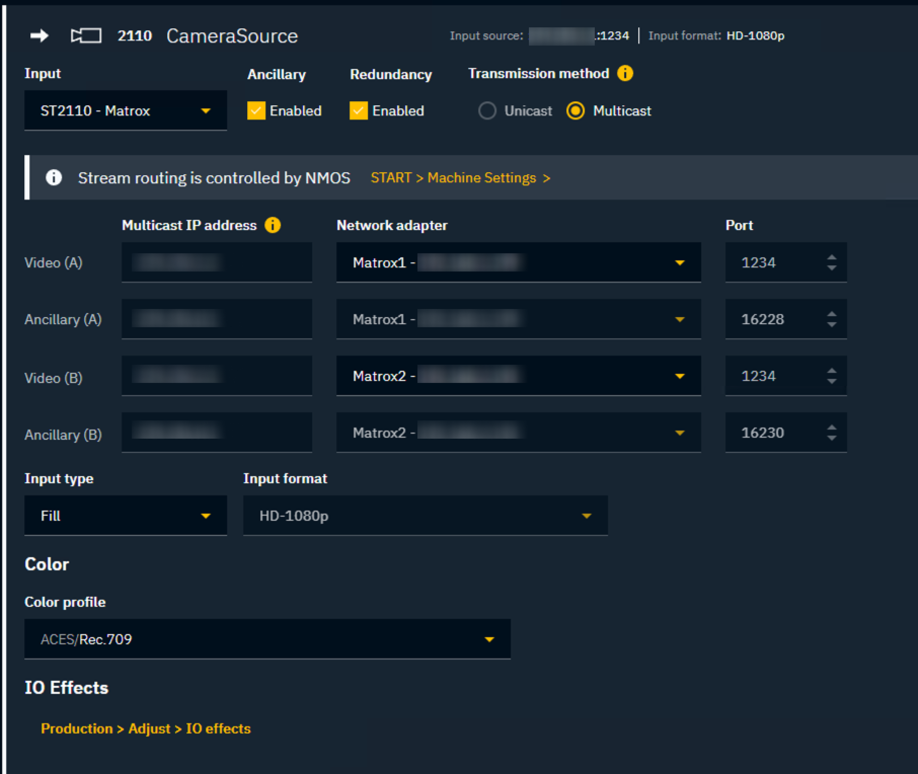
Settings specific to ST2110
-
Transmission method
-
Unicast
-
Source IP address: You can filter the source if multiple senders are unicasting to the same destination
-
-
Multicast
-
Multicast IP address: Specify the destination address of the multicast group that you want to subscribe to, to receive the desired stream from the network
-
-
-
Port
-
Destination UDP port
-
-
Network adapter
-
Select the network interface that will be used to receive this input
-
For more details see System requirements - Video cards IP
-
Ancillary
-
Option to enable an Ancillary stream (ST2110-40) associated with the video. Pixotope Graphics supports extracting timecode from the ancillary stream, and using it further in the system
-
Learn more about how to Configure timecode for 2110 below
-
Redundancy
-
Option to enable SMPTE 2022-7 network redundancy. Enabling this option will present a new set of settings for the secondary (B) path
-
Configure timecode
Learn more about how to Configure timecode (LTC)
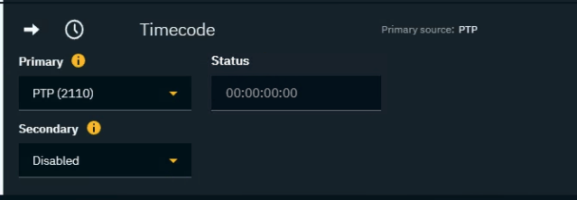
Using PTP (2110)
Extracts timecode from the PTP Grandmaster's time reference.
-
Add a Timecode item
-
Set Primary to PTP (2110)
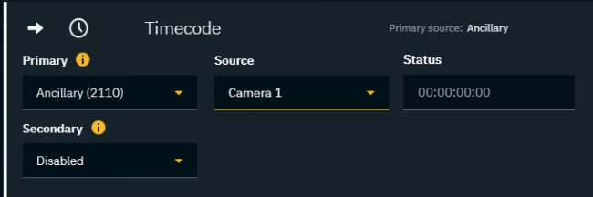
Using Ancillary (2110)
Extracts timecode from a ST2110-40 ancillary stream associated to a ST2110 video input.
-
Add a Timecode item
-
Set Primary to Ancillary (2110)
-
Choose the Source input from which to extract the timecode
-
Note that the source needs to have an associated Ancillary stream set up. See configure input
-
Configure NMOS
NMOS - Supported versions
-
NMOS API: v1.2 and v1.3
-
NMOS protocol: AMWA IS-04 and IS-05
General
NMOS defines a workflow where
-
every ST2110 system or device registers its Media Nodes
-
each of them with inputs (known as Receivers) and/or outputs (known as Senders)
-
-
an external application can create connections between Senders and Receivers, abstracting the network and transport settings
Media Node
-
Receiver (Input): The user has to indicate that it is expected to receive media in a specific network connection. When NMOS is enabled, the network settings of that input will not be configured. The idea is that a Receiver (input) will be registered in the NMOS registry, allowing the NMOS controller app to configure those settings by connecting it with a Sender of which it does have all the network settings.
-
Sender (Output): The user has to define the Multicast IP address and Port for a Sender (output). When NMOS is enabled, these settings will be registered in the NMOS registry and made available for the NMOS controller app to create connections.
Pixotope supports configuring inputs and outputs according to the NMOS protocol (AMWA IS-04 & IS-05).
Configure basic routing
Before controlling inputs and outputs from the NMOS Control Application, basic routing configuration has to be in place.
Follow the routing instructions above.
ST2110 settings after NMOS is enabled
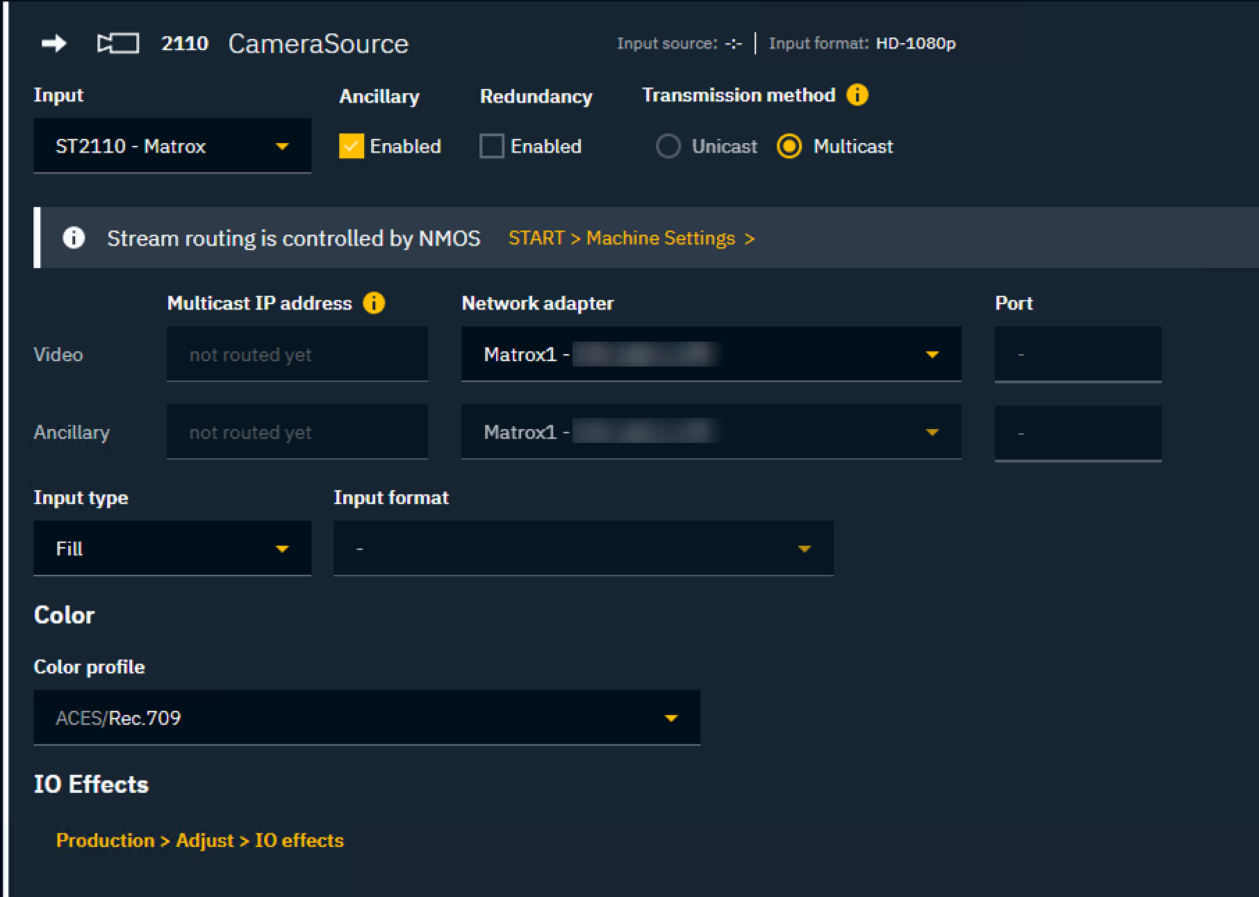
Enable NMOS
To enable NMOS in Pixotope:
-
Go to START > Machine settings > Matrox > 2110 > NMOS
-
Click "Edit"
-
Specify the IP and Port of the NMOS registry


Make sure that both the NMOS registry and the NMOS control app are in the same network as the Pixotope engines. If using complex networks, ensure NMOS traffic can flow between the Pixotope engines' network, the network containing the NMOS registry and the NMOS control app.
The Matrox card will allow NMOS communication to go through both interfaces, in case a redundant network architecture has been implemented.