Cabling
Preface
Check out the video tutorial for cabling and inputs.
Maximum Cable Range
Each to the tracking engine and assuming the use of high quality and shielded ethernet cables without active extensions, for example fiber converters.
Source | Length | Signal Type |
Sensor Camera | 70m | 1 Gbit ethernet |
IMU | 50m | RS-422 serial |
Canon lens data | 70m | RS-422 serial |
Fujinon lens data | 15m to 20m | RS-232 serial |
External Encoder | 70m | Differential quadrature |
Signal Collector Box | 70m | 1 Gbit ethernet |
For sensor camera network requirements go here.
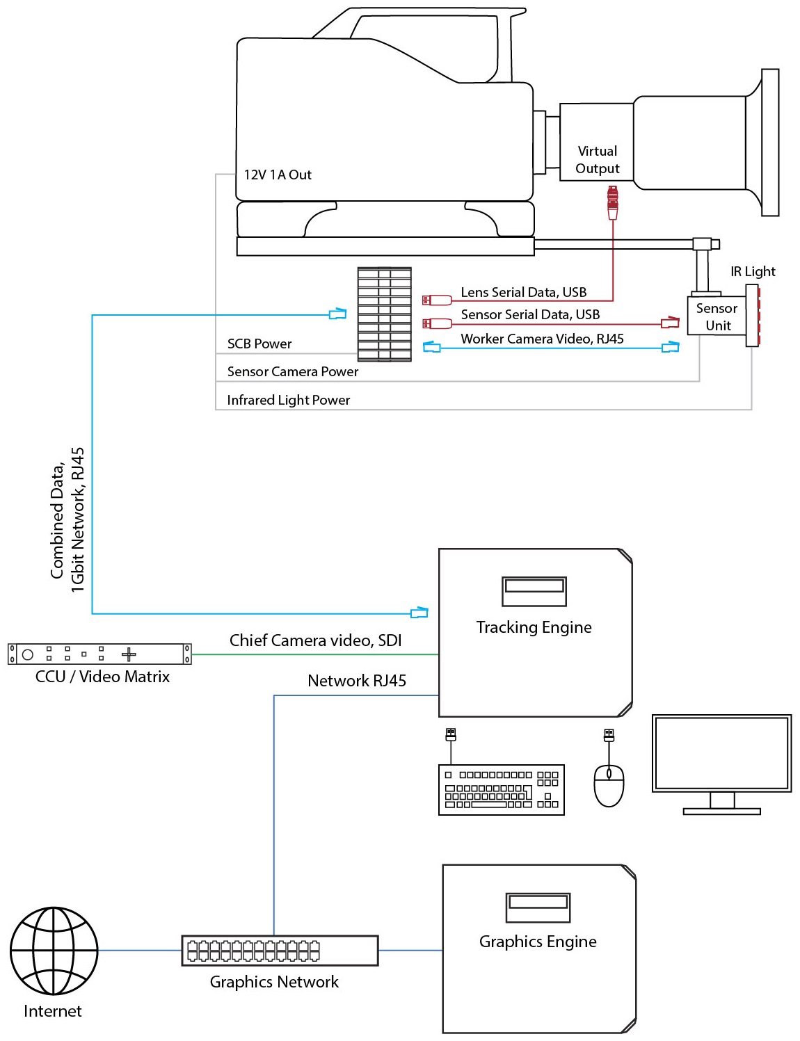
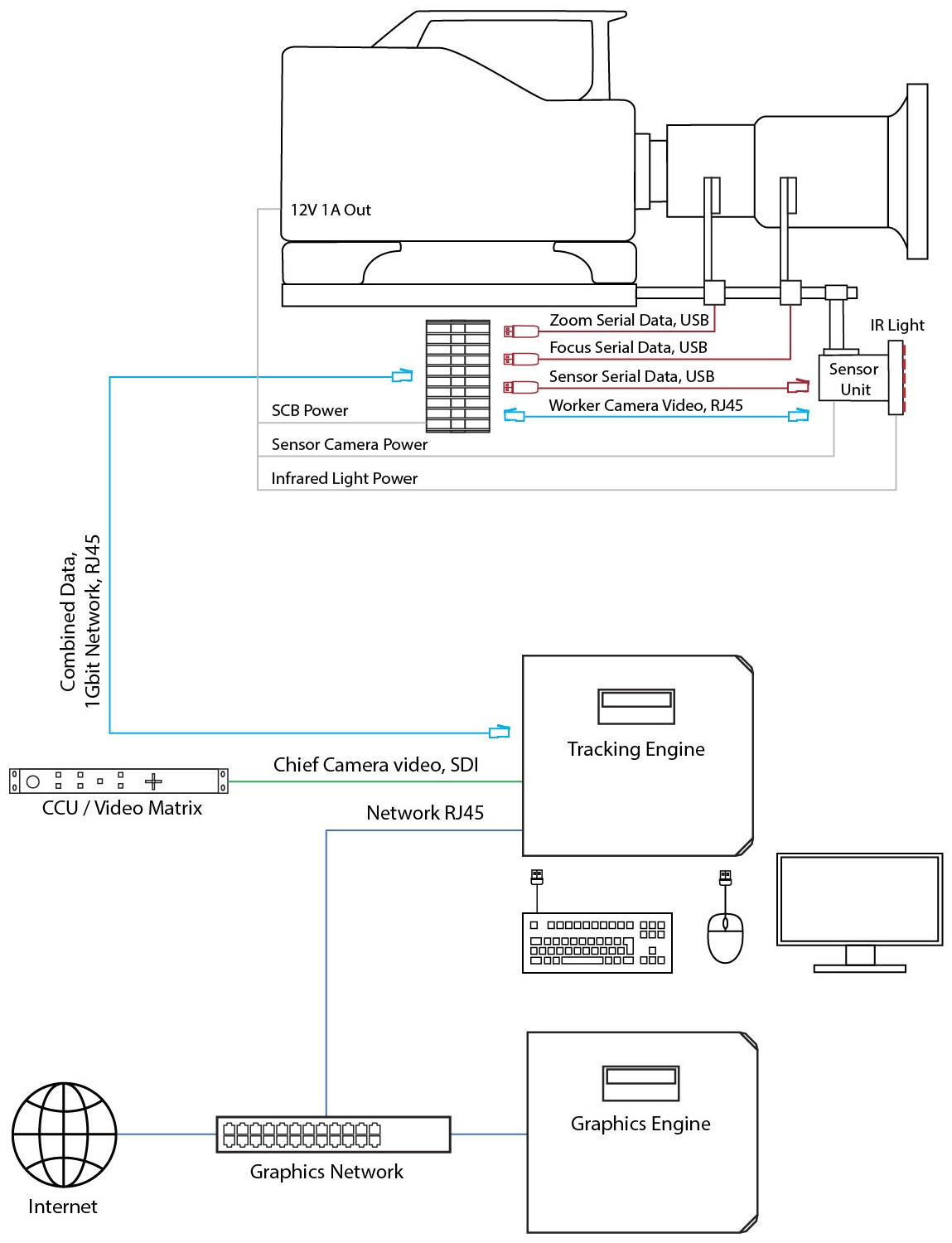
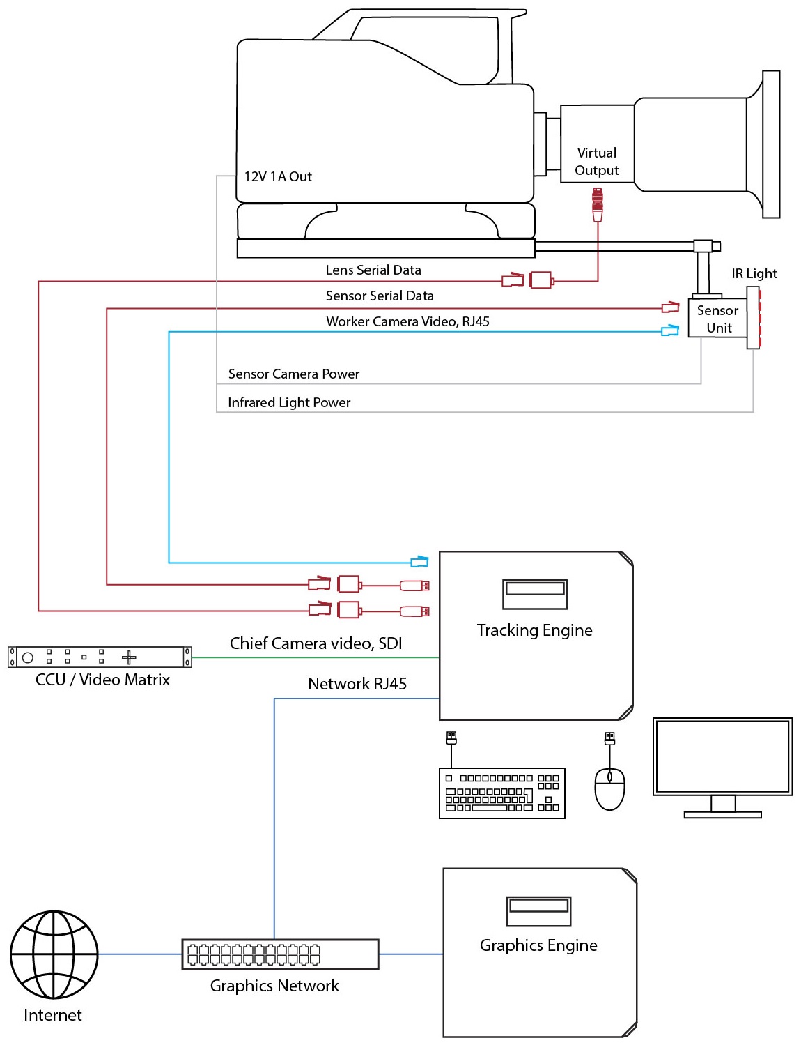
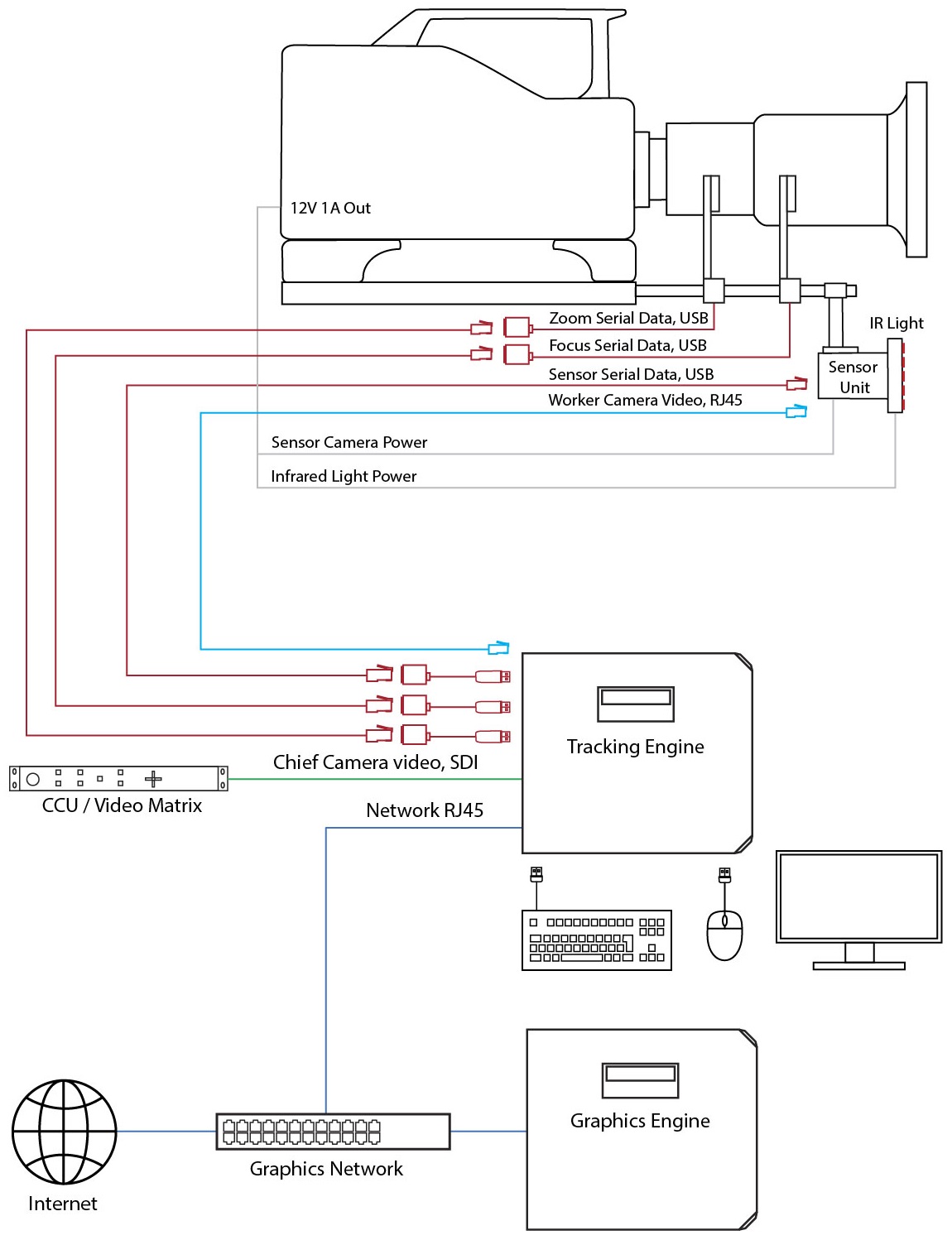
Diagrams
For more information about the Signal Collector Box, go to its Help Center page.
1 Power
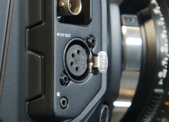
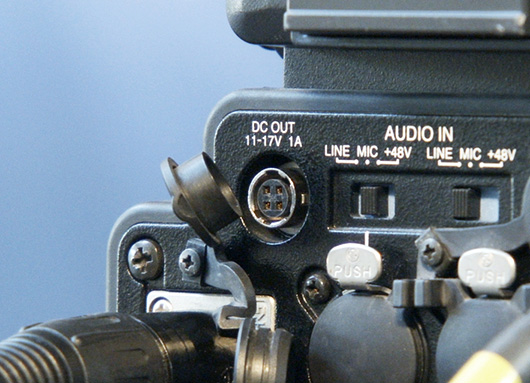
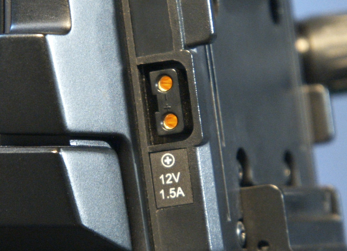
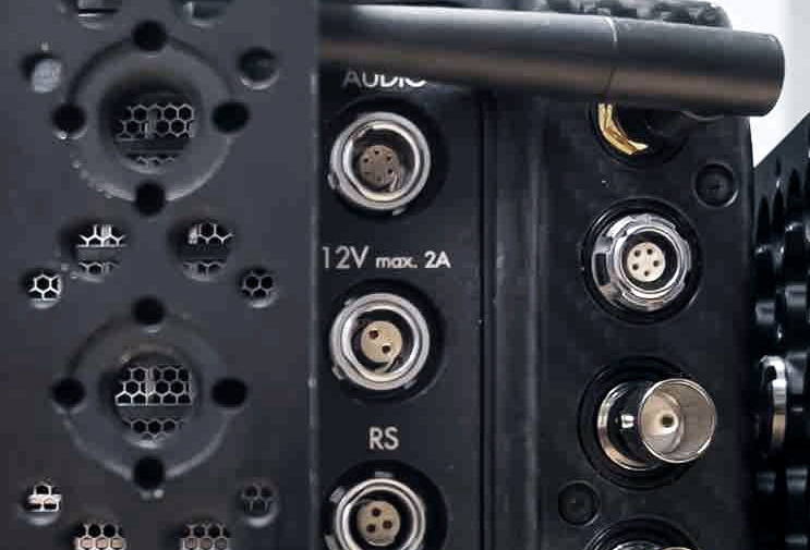
Connect the Sensor Unit power cable to sensor camera and infrared ring light and use an appropriate 4-pin XLR adapter cable to connect to the power source. The Sensor Unit needs 12V 1A.
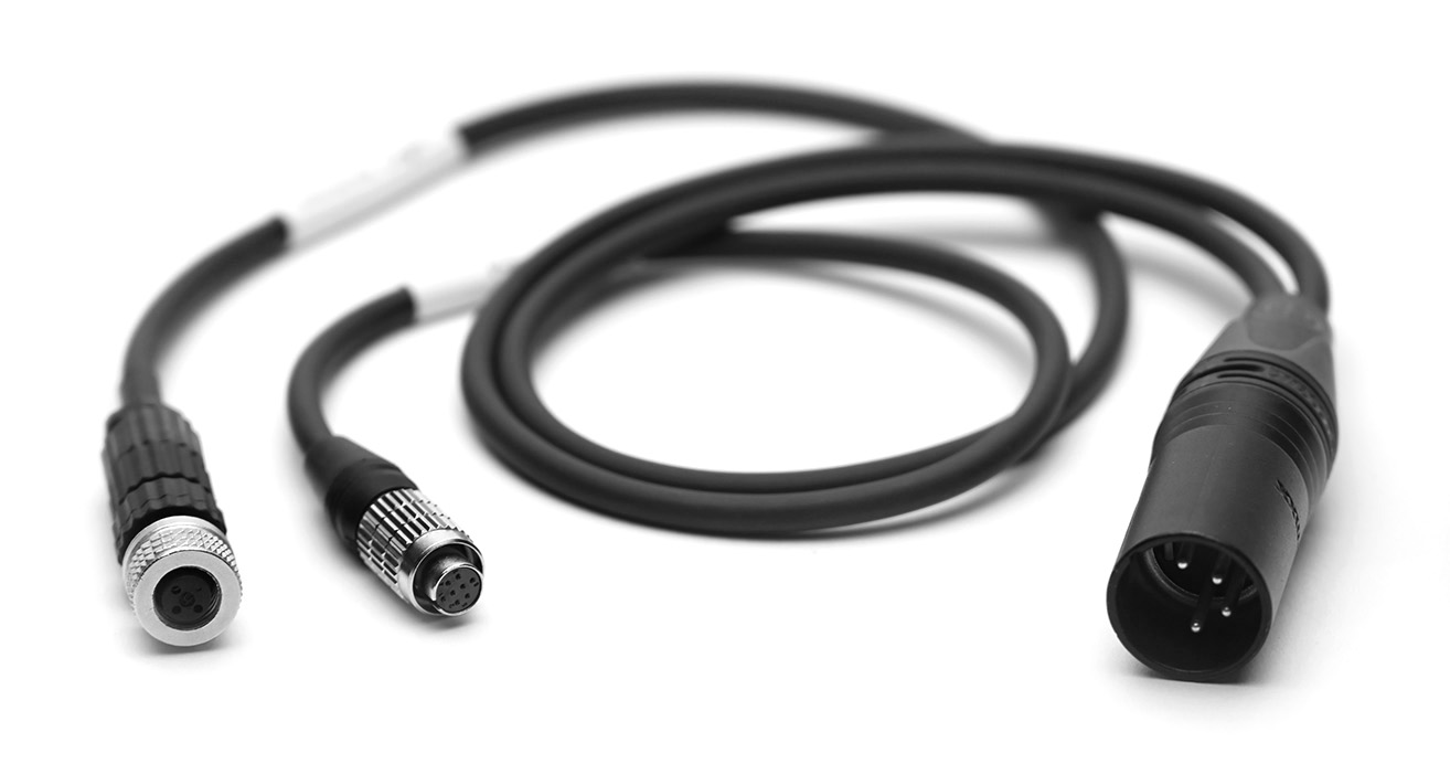
Sensor Unit power cable for Vimba camera (camera and IR ring light)
Connection Type | Adapter | Source |
|---|---|---|
XLR 4-pin |
|
 |
Hirose 4-pin | 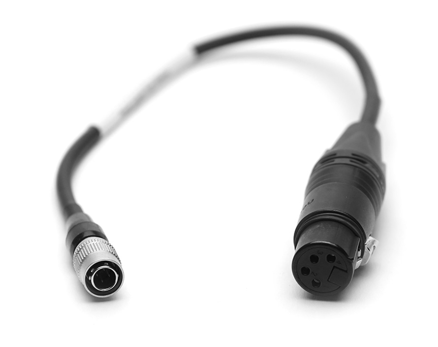 |
 |
D-Tap | 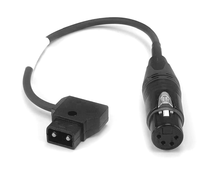 |
 |
Lemo 2-pin | 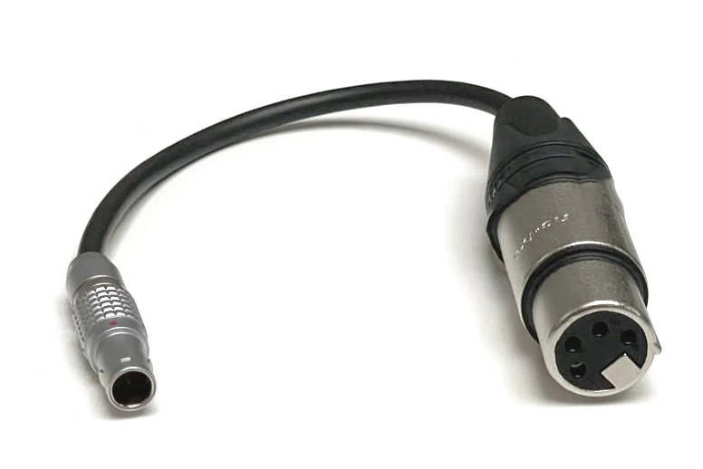 |
 |
AC power socket | 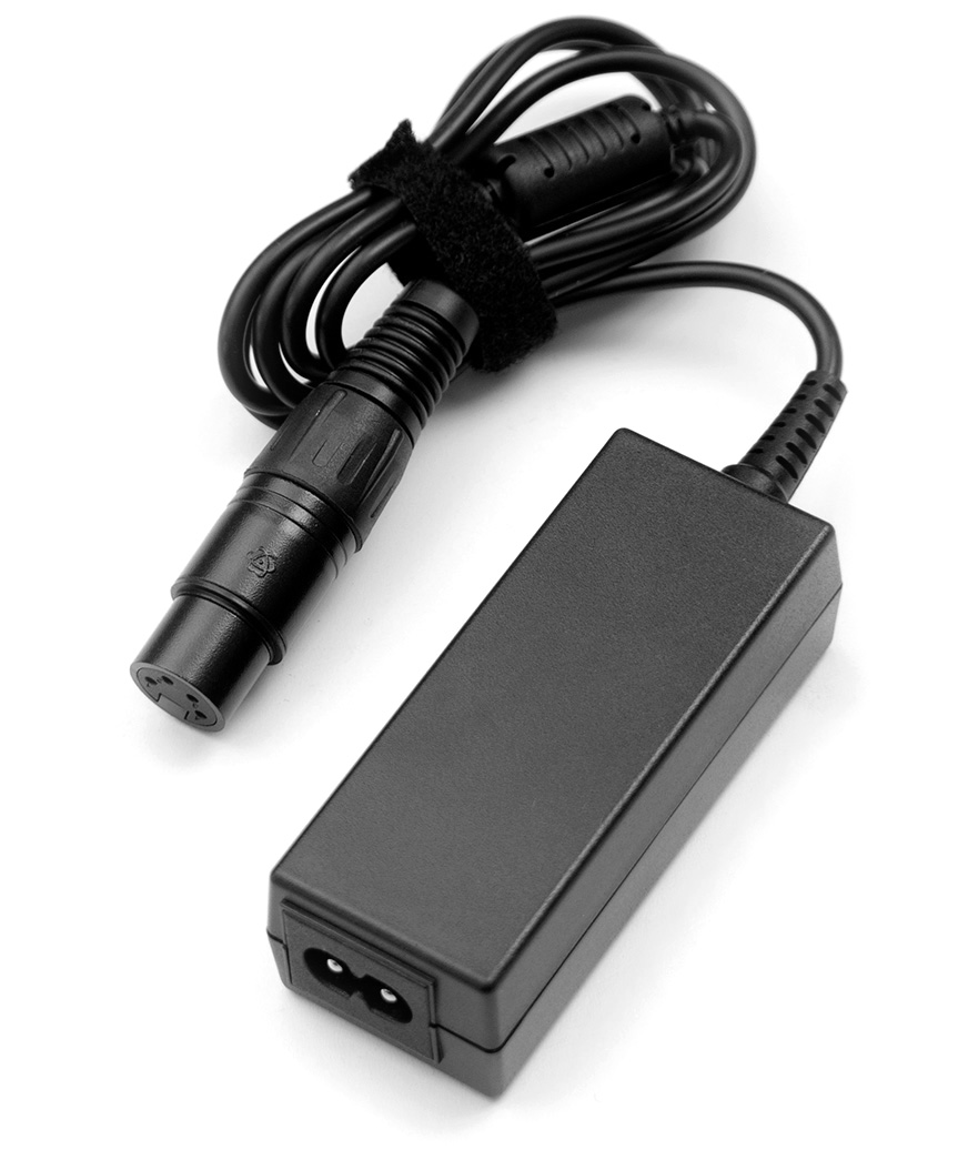 |
|
2 Sensor Camera
Connect a high quality and shielded ethernet cable (minimum cat 5e) to the sensor camera and a 1 Gbit capable ethernet port of the tracking engine. This must be a direct and exclusive connection.
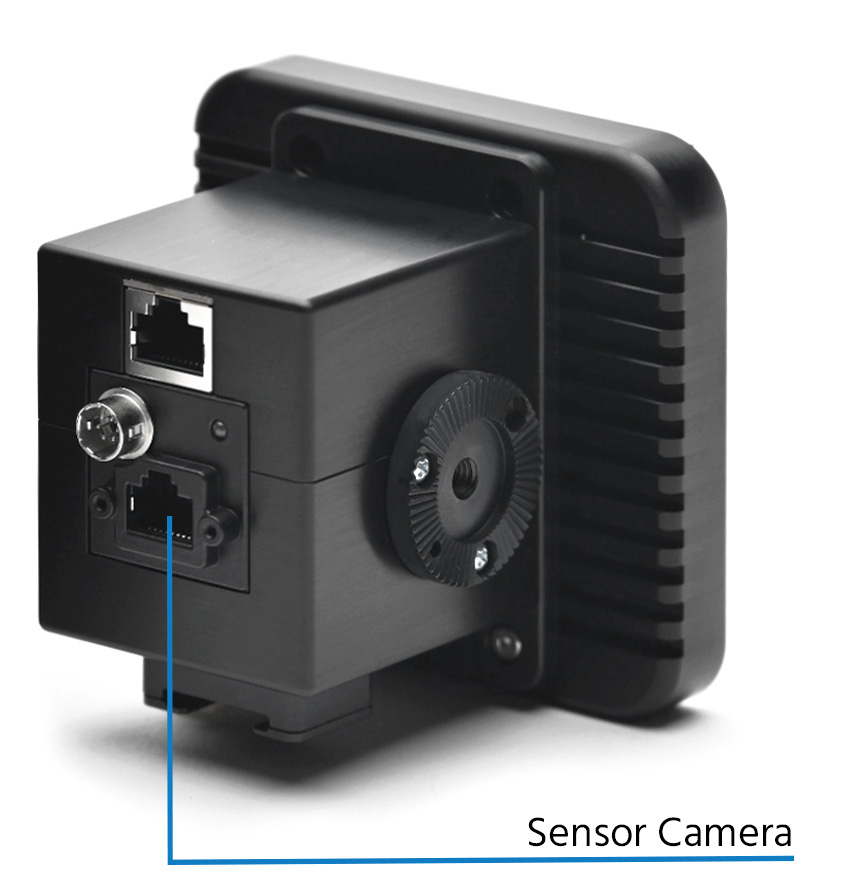
For sensor camera network requirements go here.
3 IMU
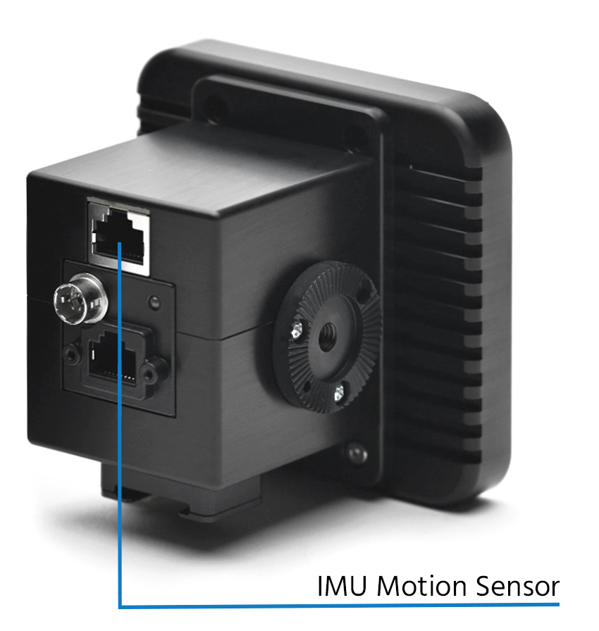
Connect a TrackMen RS422/5 to USB converter to a USB port of the tracking engine and connect it directly with a high quality and shielded ethernet cable to the sensor units IMU. The data from the IMU is RS-422 serial and not IP-based.
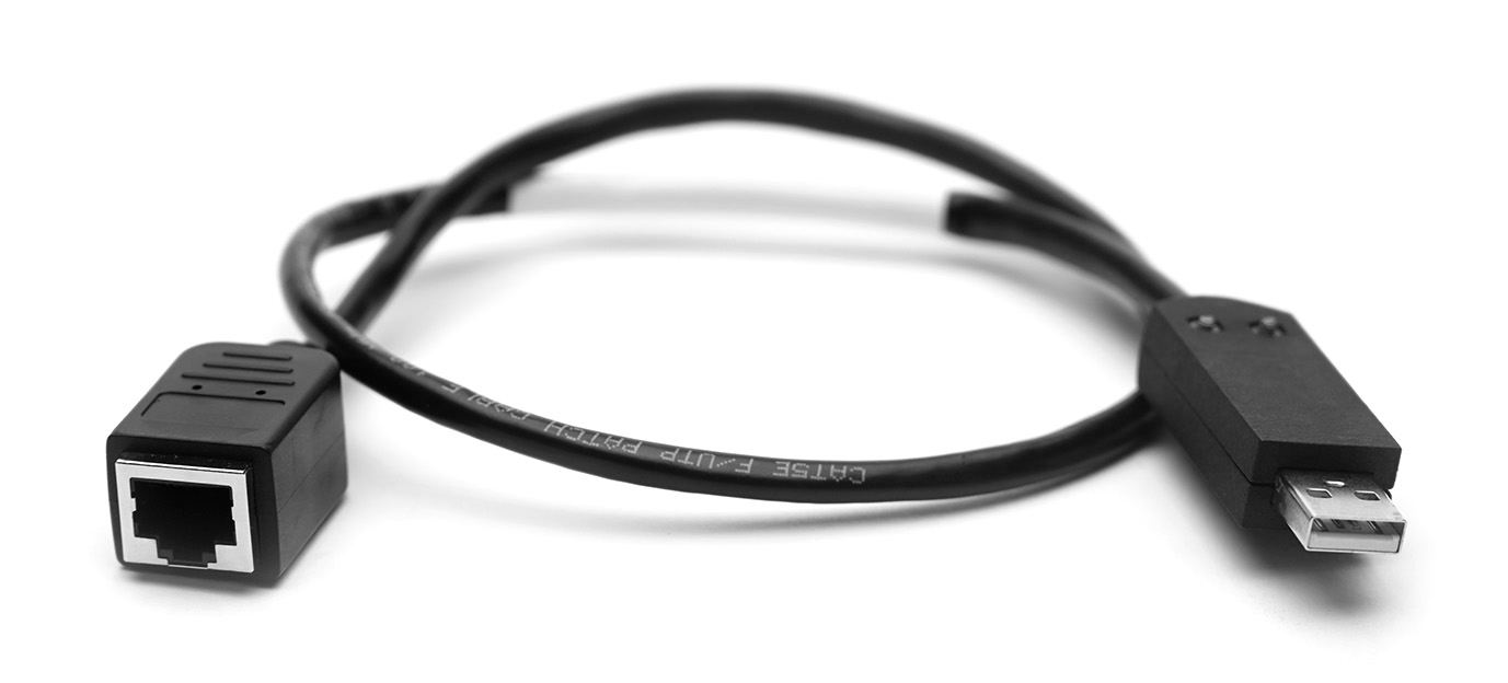
TrackMen RS422/5 to USB converter to be put in a tracking computer’s USB port
4 Lens Data
4.1 Canon
Connect the Canon lens data connector to the Virtual output on the lens and a TrackMen RS422/5-to-USB converter to a USB port of the tracking engine. Connect both directly with a high quality and shielded ethernet cable. The data from the Canon lens is RS422 serial and not IP-based.
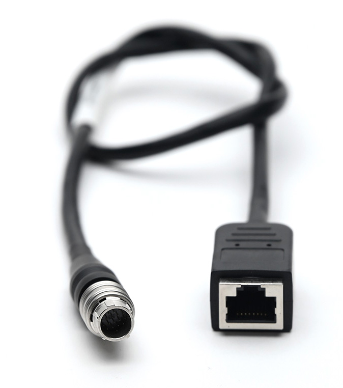
Canon lens data connector
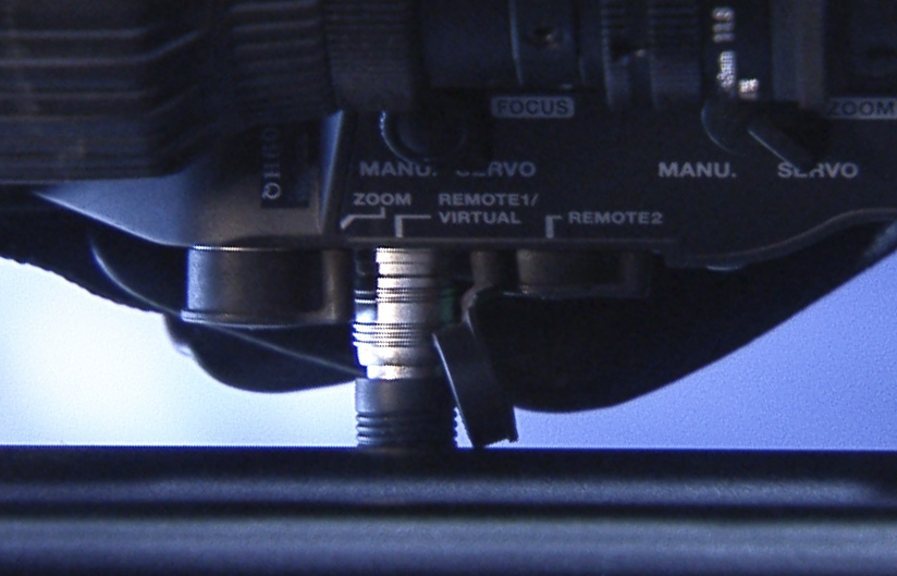
Canon lens data output

TrackMen RS422/5-to-USB converter to be put in a tracking computer’s USB port
4.2 Fujinon
Connect the Fujinon lens data connector to the EXT output on the lens. Connect the Fujinon RS232-to-USB converter to a USB port of the tracking engine. Connect both directly with a high quality and shielded ethernet cable using the included ethernet adapters. The data from the Fujinon lens is RS-232 serial and not IP-based. RS-232 limits the cable range to max. 20m, which makes the use of an SCB preferrable.
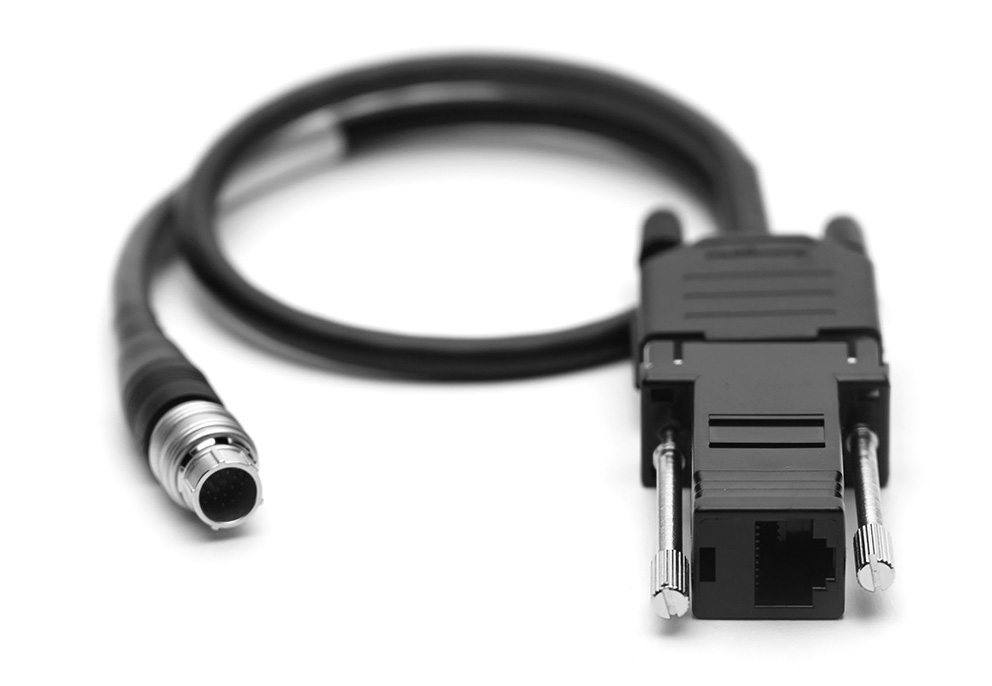
Fujinon lens data connector
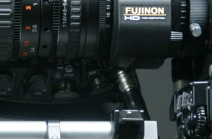
Fujinon EXT lens data output
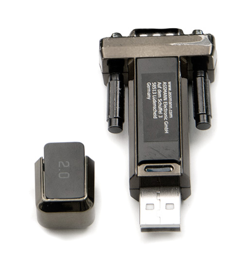
Fujinon RS232-to-USB converter to be put in a tracking computer’s USB port
4.3 External Encoder(s)
Connect a Quadrature-to-USB converter for external encoders to a USB port of the tracking engine and connect it directly with a high quality and shielded ethernet cable to the external encoder connector. The data from the external encoder is differential quadrature serial and not IP-based.
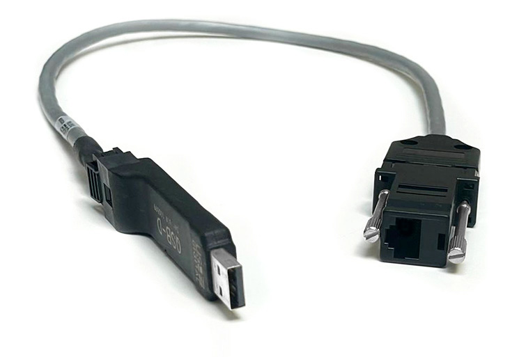
Quadrature-to-USB converter for external encoders
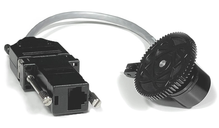
External encoder serial output
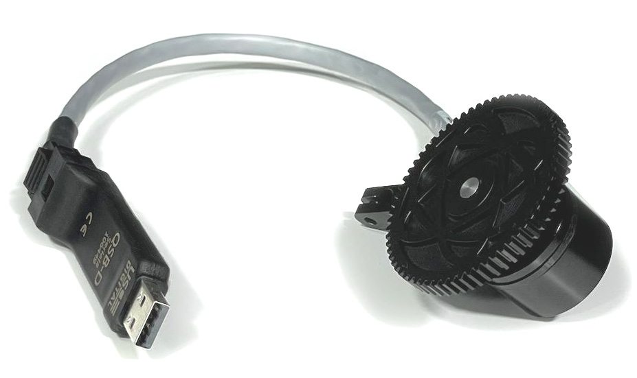
External encoder for the use with an SCB
5 SDI Video
Connect an SDI cable with the film/broadcast camera video (Chief video) to the respective video capture card in the tracking engine. It may be taken from other sources like camera CCU or video matrix. It should be undelayed and a clean feed, with no on screen menu items or other elements in it.
There is more information about the Chief video input.
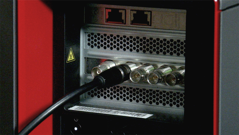
HD-SDI connector to Blackmagic Decklink video capture card in tracking engine
The Blackmagic Desktop Video Setup program comes preinstalled with the Tracking OS. It shows the current input format.
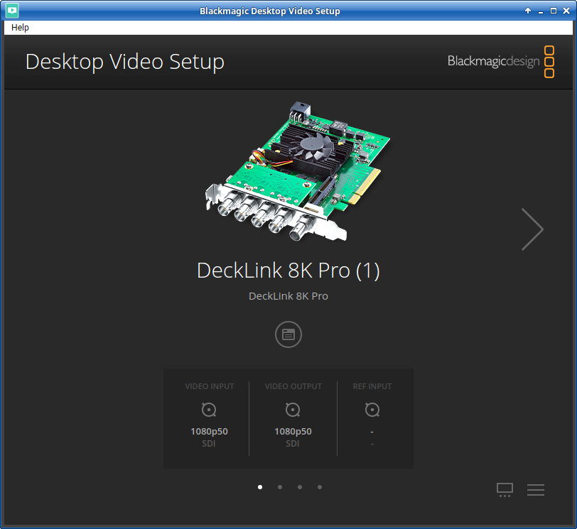
Blackmagic Desktop Video Setup accessible in Menu under Multimedia

