A mapping defines which XR walls or parts of your LED wall are rendered on which output.
-
Without a mapping, there will be no XR or digital twin pattern output.
-
The mapping process is identical for manual and digital twins
-
Mapping creation is a 2D process independent of LED body shapes
The step of creating mappings should be done after bodies were generated, either using a manual or a digital twin.
Once you have information about the LED body sizes and resolutions, you can decide:
-
How many outputs you need
-
Which scale mode to use
Create mapping: LED wall smaller than single output
When your LED wall has a lower resolution than a single Pixotope output, you can create a straightforward one-to-one mapping.
Example LED Wall Configuration
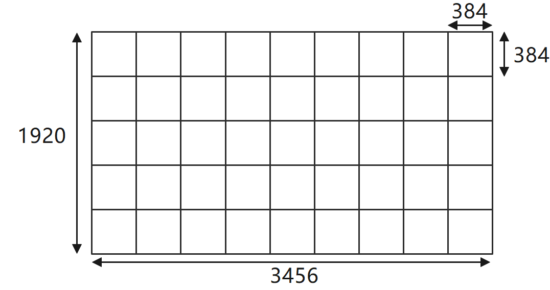
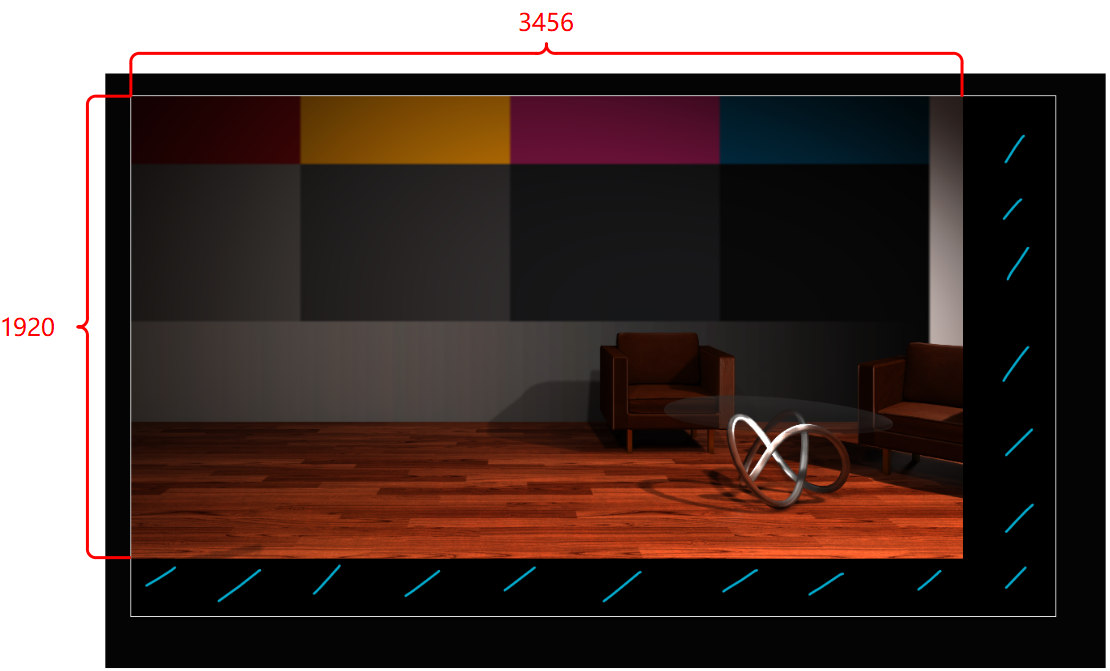
Consider an LED wall with 9 × 5 panels. If each panel has a resolution of 384 × 384 pixels, the total wall resolution would be 3456 × 1920 pixels.
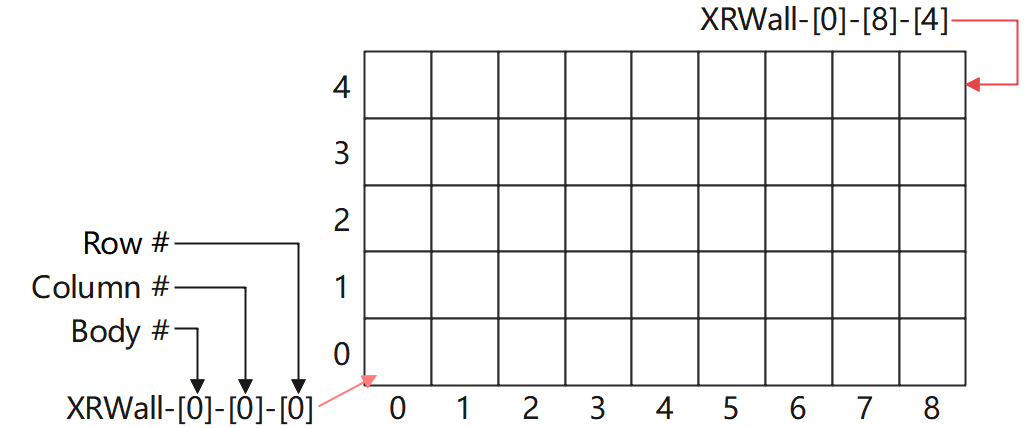
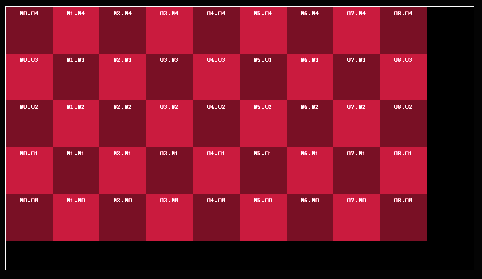
In the Digital Twin actor, LED panels (XR walls) are named starting from the bottom left panel of the LED body.
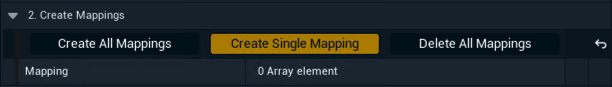
Create single mapping
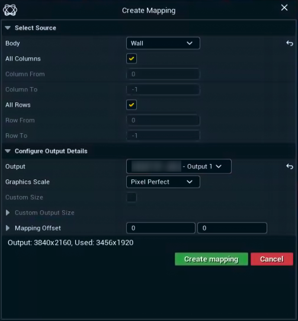
Since the resolution of this LED wall (3456 × 1920) is smaller than a single Pixotope UHD output (3840 × 2160), you can create a single mapping with these steps:
-
Open the Details panel of the Digital Twin XR Actor
-
Click "Create Single Mapping"
-
Body: Select the LED Body you want to creating a mapping for
-
Keep All Columns and All Rows selected
-
-
Output: Select the routed output the mapping should be applied to
Make sure you select the right output as all outputs from each machine in the Pixotope network are listed.
-
Graphics Scale: Choose "Pixel Perfect"
-
this ensures pixel-to-pixel display on the LED
-
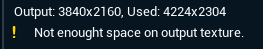
Double check the reported Output and the Used size on the bottom.
-
Click "Create the mapping"
A single mapping is created and the Output Channel of all XR walls is set to the output selected above.
Verify output
After creating the mapping, your XR output will display the texture with the following characteristics:
-
The XR texture will occupy only part of the output (3456 × 1920 pixels)
-
The unused portion of the output will appear black
-
The LED processor needs to extract the relevant pixels and display them on the physical LED wall
|
Display mode: XR |
Display mode: Identify |
|---|---|
|
|
Learn more about how to identify your mappings below
Create mapping: LED wall larger than single output
Example LED Wall Configuration
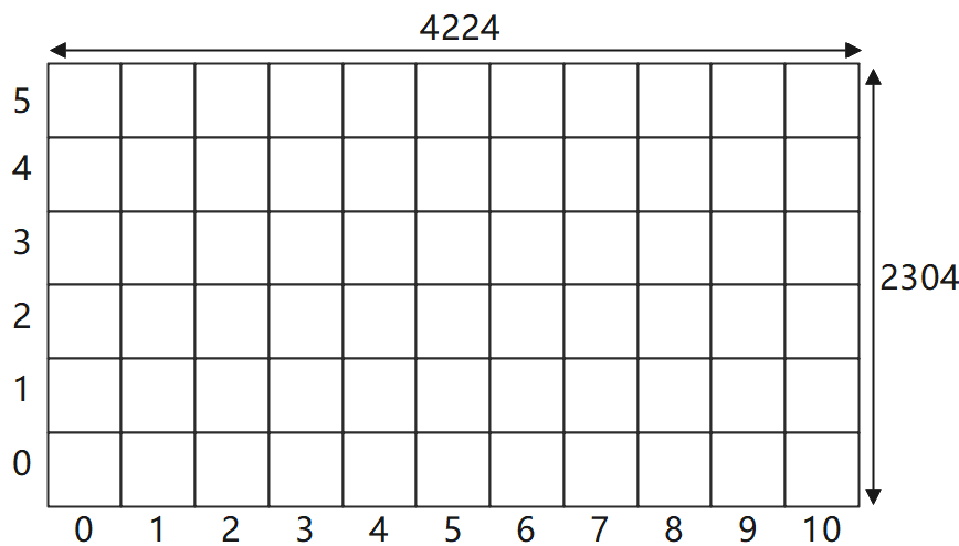
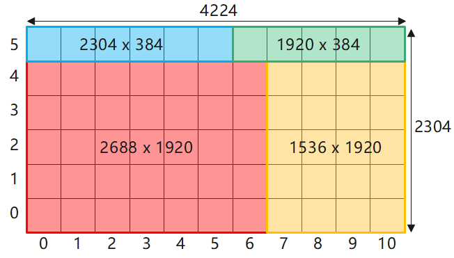
Consider an LED wall with 11 × 6 panels. If each panel has a resolution of 384 × 384 pixels, the total wall resolution would be 4224 × 2304 pixels. This exceeds the size of UHD.
For larger LED walls with resolutions exceeding a single Pixotope output, you have 2 options:
Option 1: Scale to Fit
-
Allows you to use a single output but sacrifices resolution quality
-
Can work well for testing or demonstrations but may not be ideal for production
-
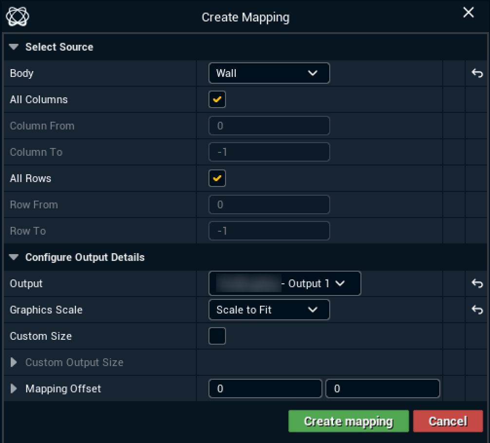
Open the Details panel of the Digital Twin XR Actor
-
Click "Create Single Mapping"
-
Body: Select the LED Body you want to creating a mapping for
-
Keep All Columns and All Rows selected
-
-
Output: Select the routed output the mapping should be applied to
-
This "squeezes" the entire wall resolution into a single output
-
-
Graphics Scale: Choose "Scale to Fit"
-
This removes the Not enough space warning
-
-
Click "Create the mapping"
Verify output
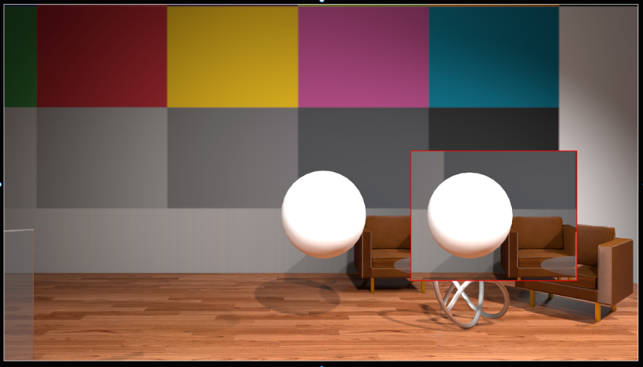
After creating the mapping, your XR output will display the texture with the following characteristics:
-
The XR texture takes up the entire output image
-
It reduces the XR engines at the cost of resolution loss
-
In our example we lost 14.77% resolution
-
-
Depending on the aspect ratio difference, the output image can look squeezed compare to the pixel perfect output
-
Don’t worry! The texture will be stretched back to the normal size when displayed on the LED wall
-
Option 2: Pixel Perfect with Multiple Outputs
For best quality
-
Divide your LED body into pieces that can each fit within an output
For optimal performance
-
Distribute pixels evenly across outputs to balance rendering load
-
Uneven distribution can cause frame drops on heavily loaded machines
-
Note: This can be ignored if all outputs come from the same machine
-
Manual division
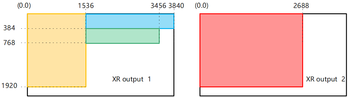
Example division
Example mapping layout
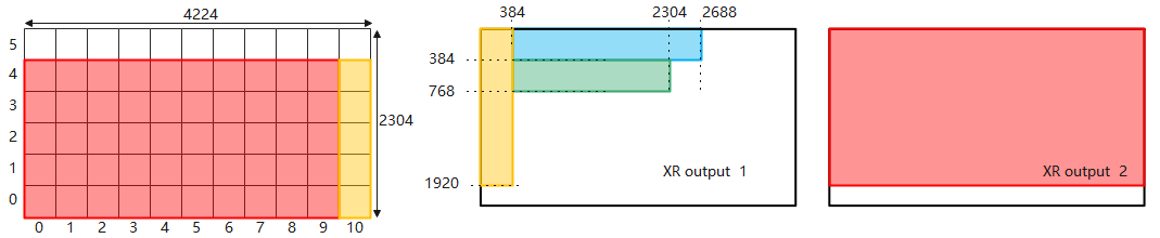
Alternative mapping layout
You can also make pixel perfect mappings in other layouts.
OR
For every single mapping, it starts with opening the Create Single Mapping dialog
-
Open the Details panel of the Digital Twin XR Actor
-
Click "Create Single Mapping"
-
Body: Select the LED Body you want to creating a mapping for
-
Set the columns, rows and offset based on your mapping layout
|
|
Columns |
Rows |
Offset x |
Offset y |
|---|---|---|---|---|
|
Mapping 1 (red) |
0-6 |
0-4 |
0 |
0 |
|
Mapping 2 (yellow) |
7-10 |
0-4 |
0 |
0 |
|
Mapping 3 (blue) |
0-5 |
5-5 |
1536 |
0 |
|
Mapping 4 (green) |
6-10 |
5-5 |
1536 |
384 |
-
Output: Select the routed output the mapping should be applied to
-
Graphics Scale: Choose "Pixel Perfect"
-
Click "Create the mapping"
-
Repeat for each mapping
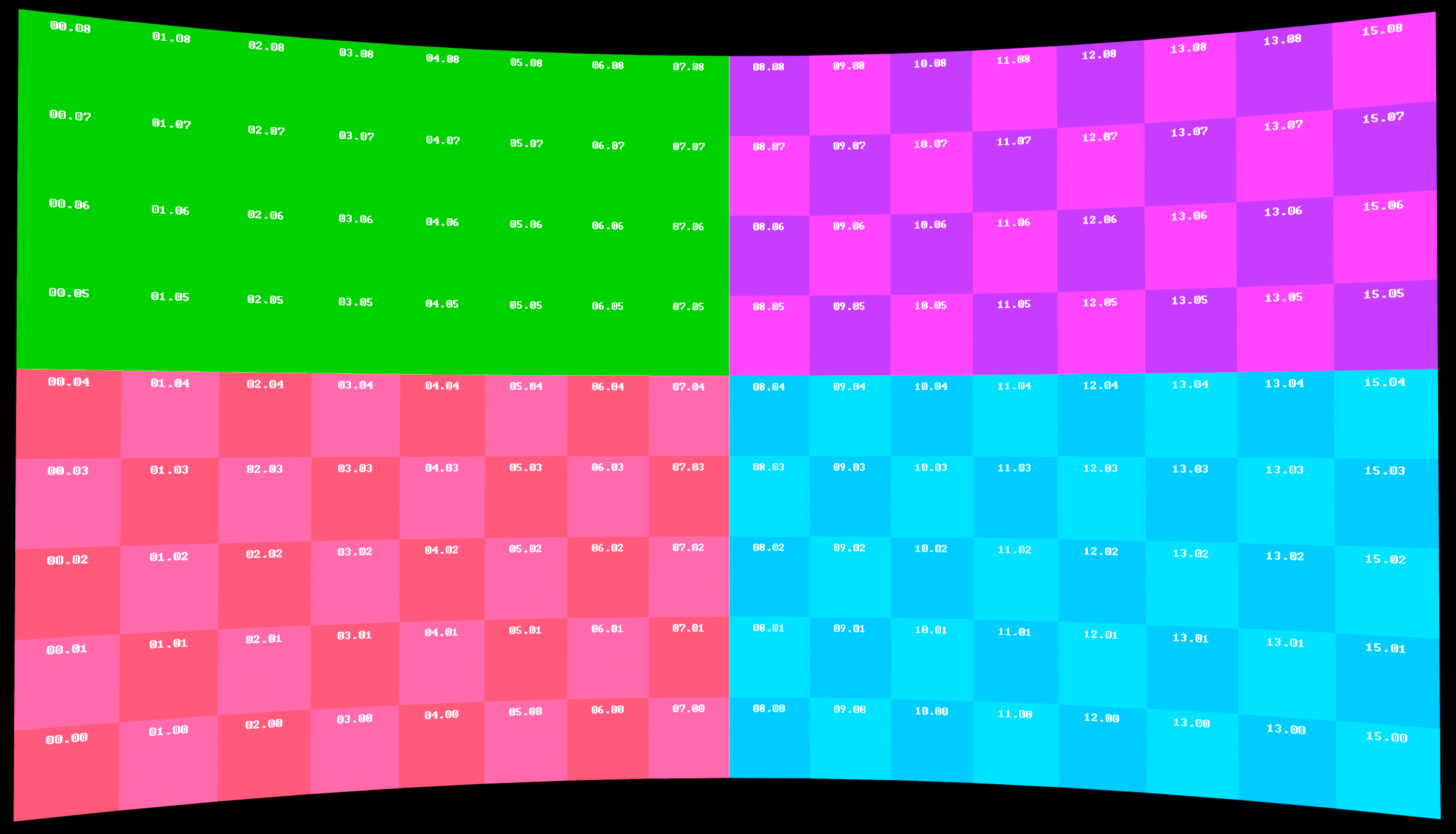
Now we have both XR output mapped with XR texture. Let’s see how they look.
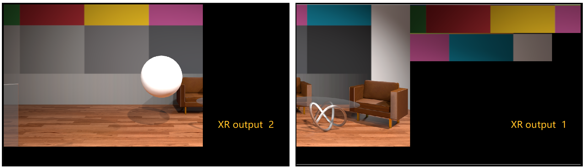
Remember to correctly position and crop each part on the LED processor.
Automatic division
Create all mappings
This option is only available for manual twins.
You can create all mappings at once.
-
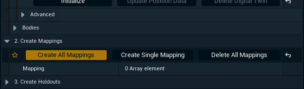
Open the Details panel of the Digital Twin XR Actor
-
Click "Create All Mappings"
-
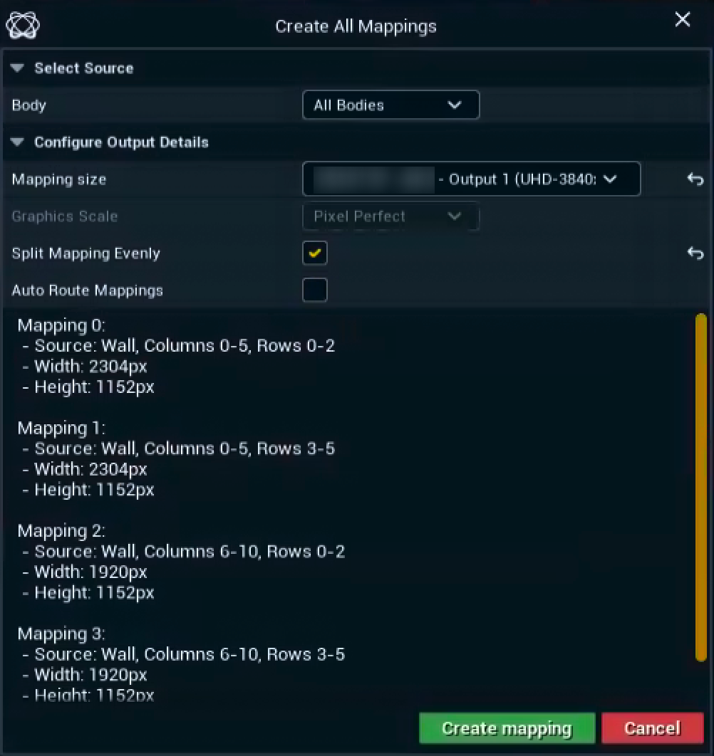
Select the LED Body you want to creating a mapping for
-
All Bodies is selected by default
-
-
Select a routed output to specify the mapping size
-
The graphics scale is fixed to Pixel Perfect
-
-
Enable Split Mapping Evenly to balance the distribution of rows and columns between mappings
-
By default a single mapping would cover as many rows as possible
-
-
Enable Auto Route Mappings to automatically assign outputs of machines to the output channel of the created XR walls/mappings
-
To change this later see Select output machines below
-
-
Click "Create mapping"
Select output machines
In a multi-machine setup you can specify which mapping should be rendered by which machine.
From Director
-
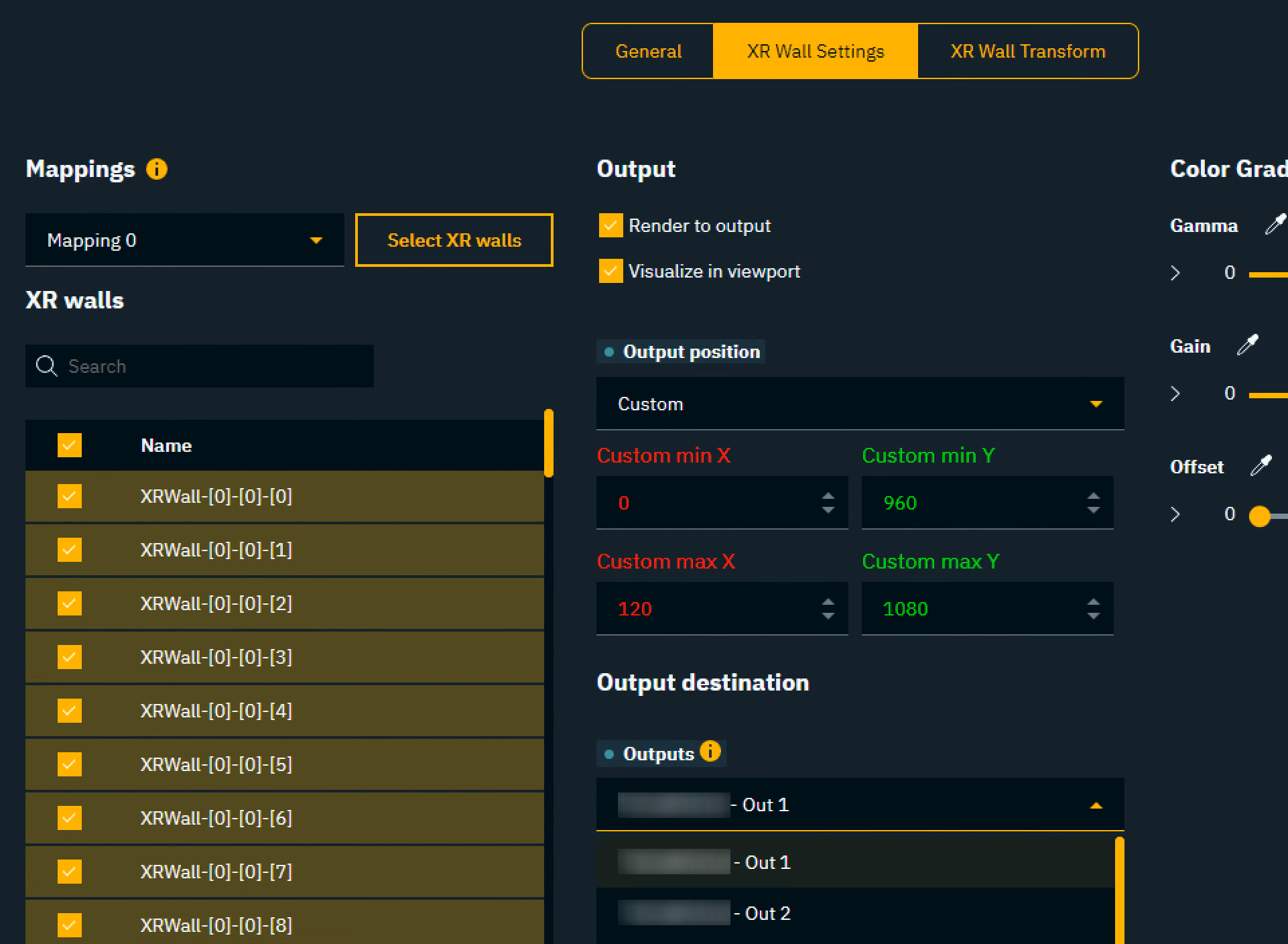
Go to the "XR wall settings" tab in PRODUCTION > Adjust > XR
-
Select the mapping/XR walls to specify the machine and output for
-
Choose the correct output from Output destination > Outputs
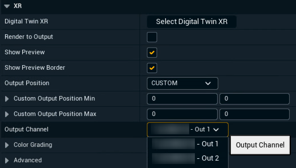
From Editor
-
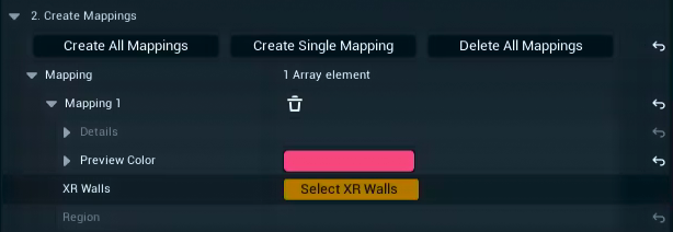
Expand the details of a specific mapping and click on "Select XR walls"
-
The detail view switches to the XR walls related to this mapping
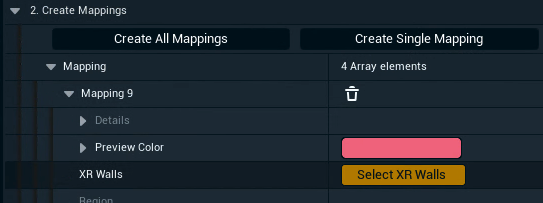
-
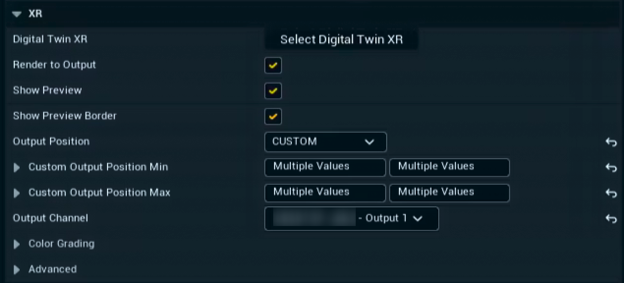
-
Select the correct output from Output channel
Identify your mappings
To check that your mappings have been setup and output correctly.
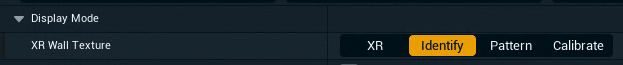
In Editor
-
Expand Display Mode
-
Choose "Identify" for the XR Wall Texture
In Director
-
Go to PRODUCTION > XR > General
-
Choose "Identify" for the Display mode for digital/manual twin
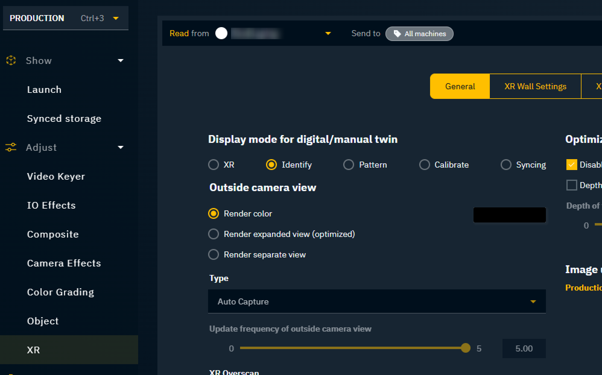
Be sure to read from the XR machine to enable the settings in the Production page.