Tracking Area
For optical tracking systems the tracking area must provide visual features. Visual features best recognized are high-contrast corners. These can exist in the real world environment for example in the form of real environment structures or text, logos, stickers or lights. To be independent from lighting and changes in the tracking area, they can be created by placing infrared markers.
Pixotope Vision: works without and/or with infrared markers simultaneously
Pixotope Marker: works only with infrared markers
Workflow
Camera positions/movements on-air → determines tracking area (following chapter) and sensor mounting
Distance from mounted sensor to markers → determines marker size (chapter 2)
Based on the above, markers are put in place in the described way (chapter 3)
Sensor is mounted and connected to the tracking engine (Cabling)
Sensor video is controlled to examine the visibility from all camera positions
If necessary, more markers are added
Mounting of sensor unit, including the angle, can be optimized, to see more markers
1 Tracking Area
1.1 Floor
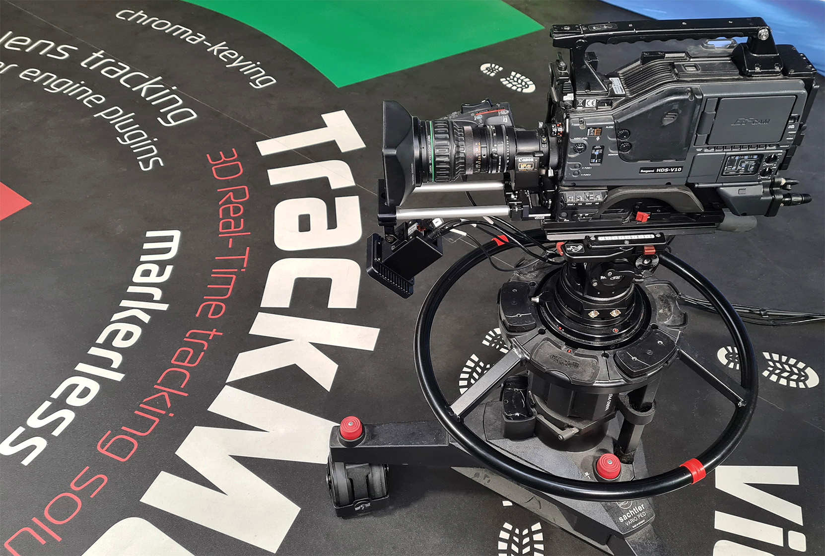
Illustration 1: Using text and structures on the floor for tracking
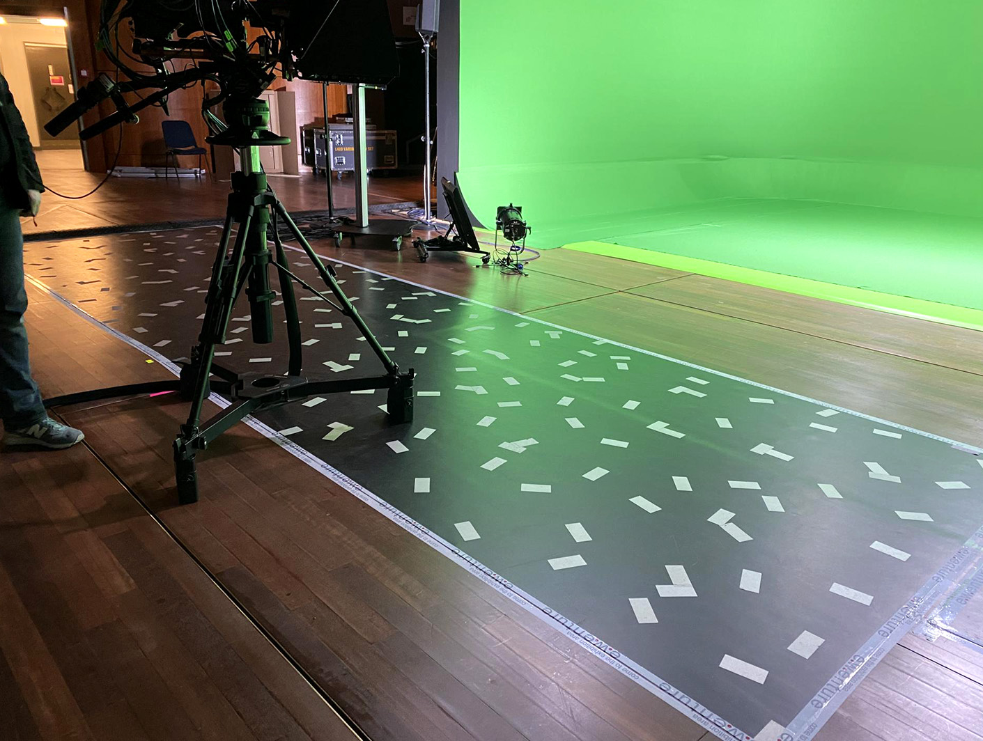
Illustration 2: Example using stickers on the floor for tracking
In many cases using the floor will provide the highest precision while at the same time making the calibration easier. This is due to the fact that virtual elements are often placed on the floor. The proximity between feature points and graphics comes with many advantages. Using the floor can however also limit the movement area of the camera, because the sensor camera always needs to see many feature points. Besides that, floor areas are prone to be obstructed by objects placed on it or the pedestal.
1.2 Ceiling
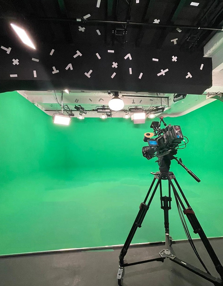
Illustration 3: Low ceiling with 5x15cm sticker markers
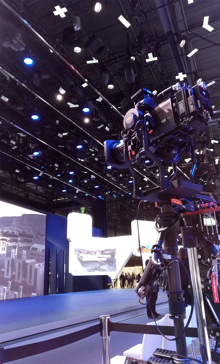
Illustration 4: High ceiling with 15x45cm marker plates
Using the ceiling as tracking area provides the most freedom of movement for the camera. Markers can be placed in the ceiling to keep the tracking system independent of changes, for example in the lighting. Minor changes in lighting are ignored by the tracking system. Significant changes in lighting can be solved by either quickly updating the reconstruction with a few keyframes or creating a new one. The marker size depends on the height of the tracking are. Tracking areas higher than 7m should use 10x30cm markers or bigger.
2 Reflective Markers
The markers consist of retroreflective material and come either in the form of stickers in sizes 5x15cm or 10x30cm or in the form of solid marker plates in the size 15x45cm. The plates can for example be mounted with metal clamps to rods in the ceiling. Tracking areas further away than 7m should use 10x30cm markers or bigger.
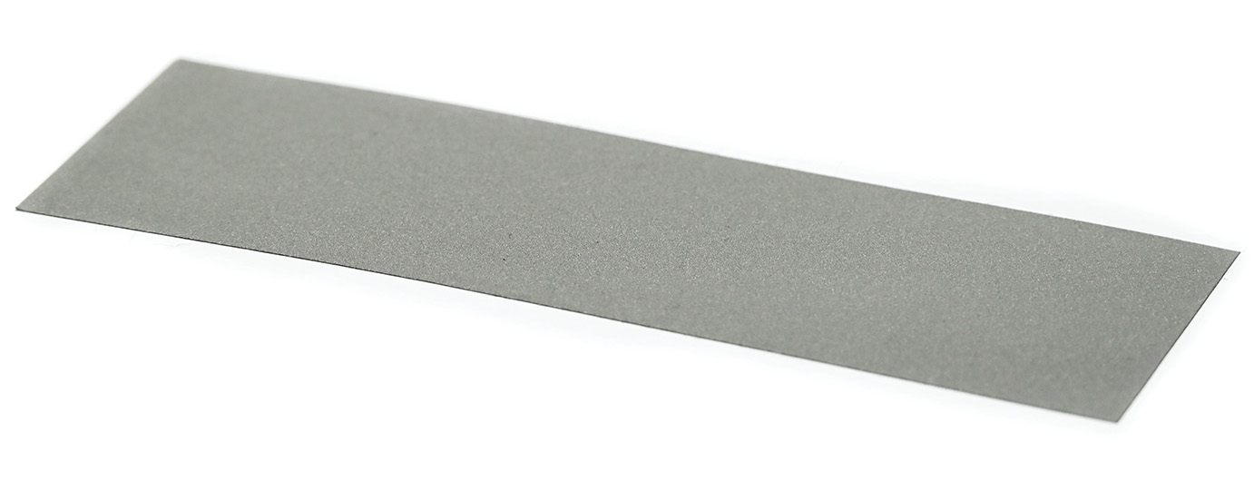
Illustration 5: Marker sticker 5x15cm
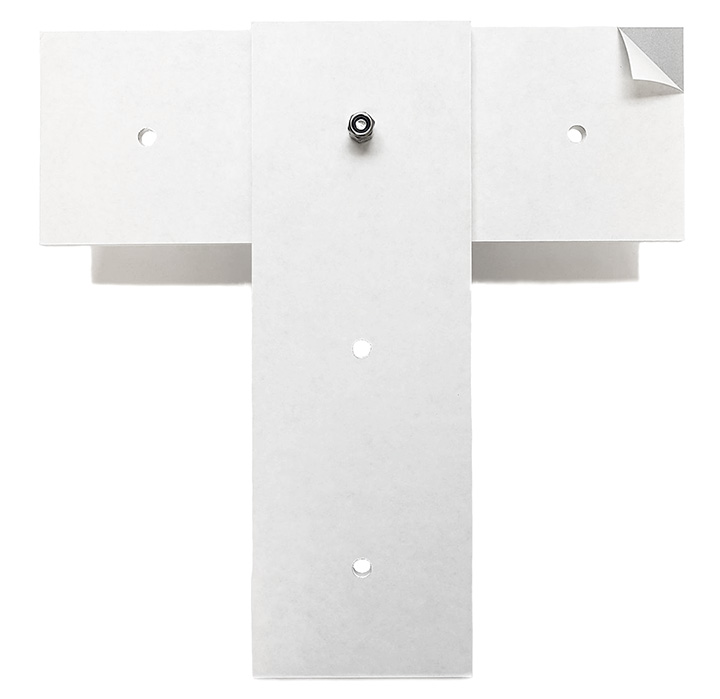
Illustration 6: 15x45cm marker plates front
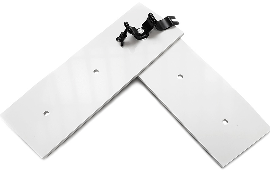
Illustration 7: 15x45cm marker plates back
2.1 Daylight and Infrared Light
Both Pixotope Vision as well as Marker systems see the markers by using infrared light. The difference is that Marker systems can only see infrared light, whereas Vision systems see infrared additionally to the natural light.
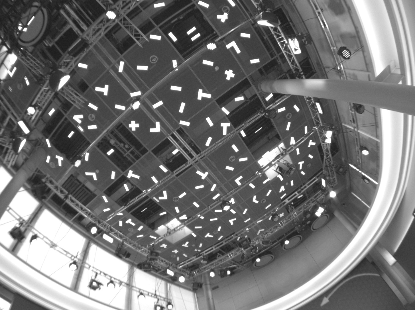
Illustration 8: View of a Pixotope Vision sensor camera onto 10x30cm marker stickers
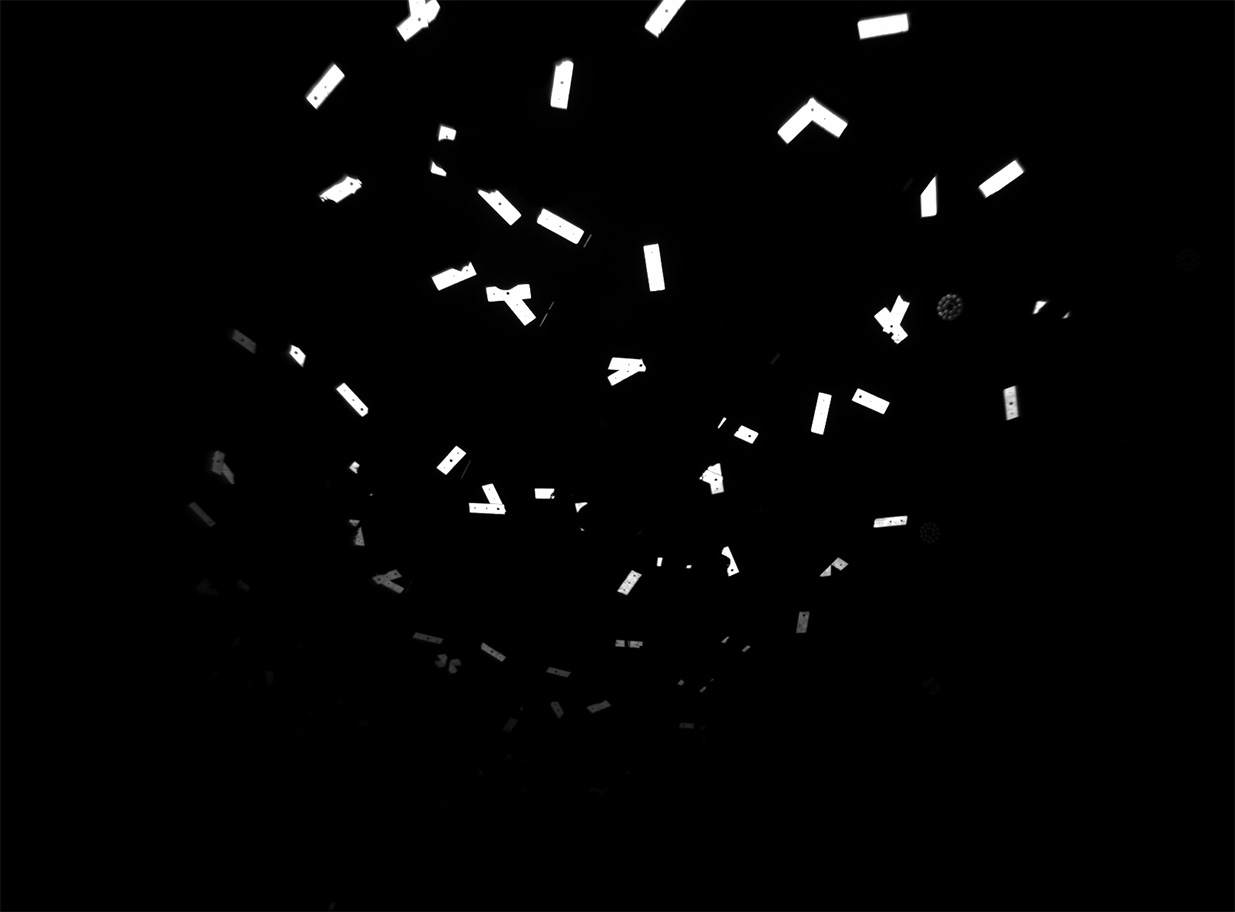
Illustration 9: View of a Pixotope Marker sensor camera onto 15x45cm marker plates
2.2 Material
Using markers from Pixotope ensures the optimal brightness and reflection angle characteristics. Other reflective material provides worse qualities of these characteristics. Therefore there can be no guarantee for the system to works as desired when not using Pixotope’s marker material. On the right you can see different retroreflective materials seen through the sensor camera from 3 different angles. They are illuminated by its infrared light.
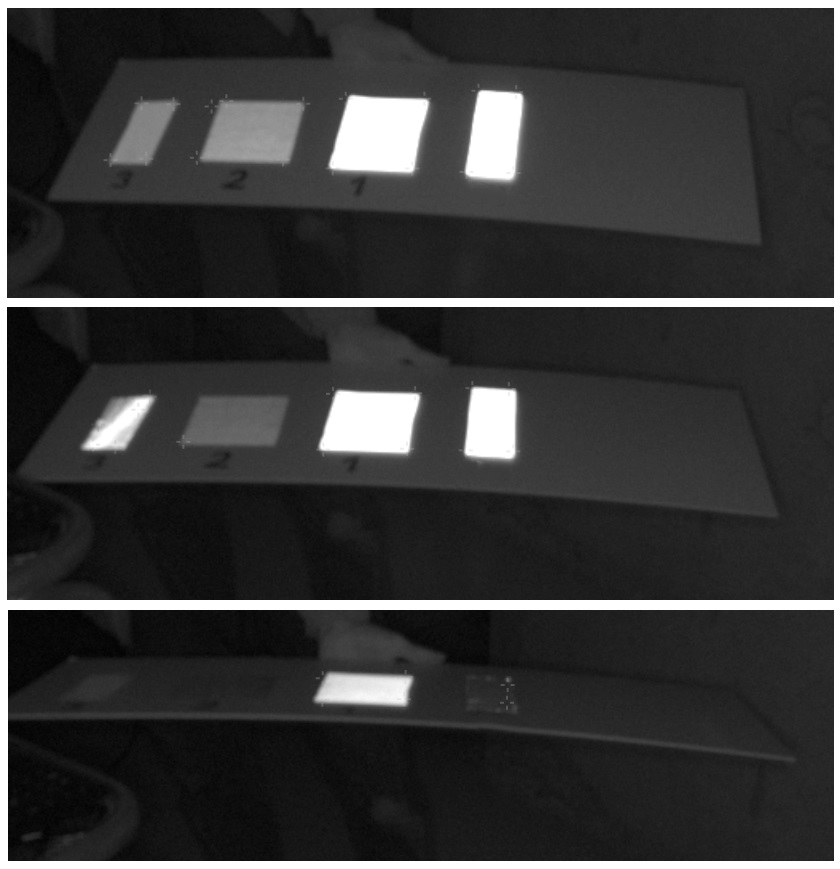
Illustration 9: Different characteristics of retroreflective materials
3 Marker Pattern
Equally distributed over the entire tracking area
approx. 50cm between stickers on the floor or low ceilings
approx. 1m between stickers on the ceiling of at least 5m height
approx 1.5m between large ceiling stickers
Each marker in a different angle and in different distances to the others to create a pattern as unregular as possible
Additional markers consisting of two or three stickers in L, T, V or X shapes in all areas
Having markers in different distances to the sensor is beneficial
