1 Preface
With its super fast and easy setup Zone Tracking makes professional-level camera tracking possible for any camera in a sports venue environment. This reduces the barrier to use live AR graphics to a minimum.
No hardware is needed on the camera, the software works solely with a video input, which makes it suitable for remote productions.
It can work with any graphics vendor and sends full 3D data, including position, orientation, field of view, lens distortion etc..
2 Requirements
-
Camera is in a fixed location, meaning only pan, tilt and zoom/focus are changed
-
Camera films a sports venue from a large distance. Zone can not be used in studios
-
The camera should be levelled horizontally.
-
The same system requirements as for other Pixotope Tracking products apply to the Zone Workstation
-
Besides the tracking workstation the only hardware needed is the Pixotope calibration board to create the lens file. This is a process of only a few minutes
-
Zone can be used with zoom and focus changes. Just like with Pixotope Fly, the zoom range is limited by how many visual features are still in frame when zooming in
-
The video signal being used should be progressive. Interlacing the video frames undermines the image processing. Possible formats are 720p and 1080p. These can be downconverted from UHD format. Upconverting an interlaced video to progressive will contain interlacing artefacts, that will decrease precision; same applies for compressed video
3 Setup
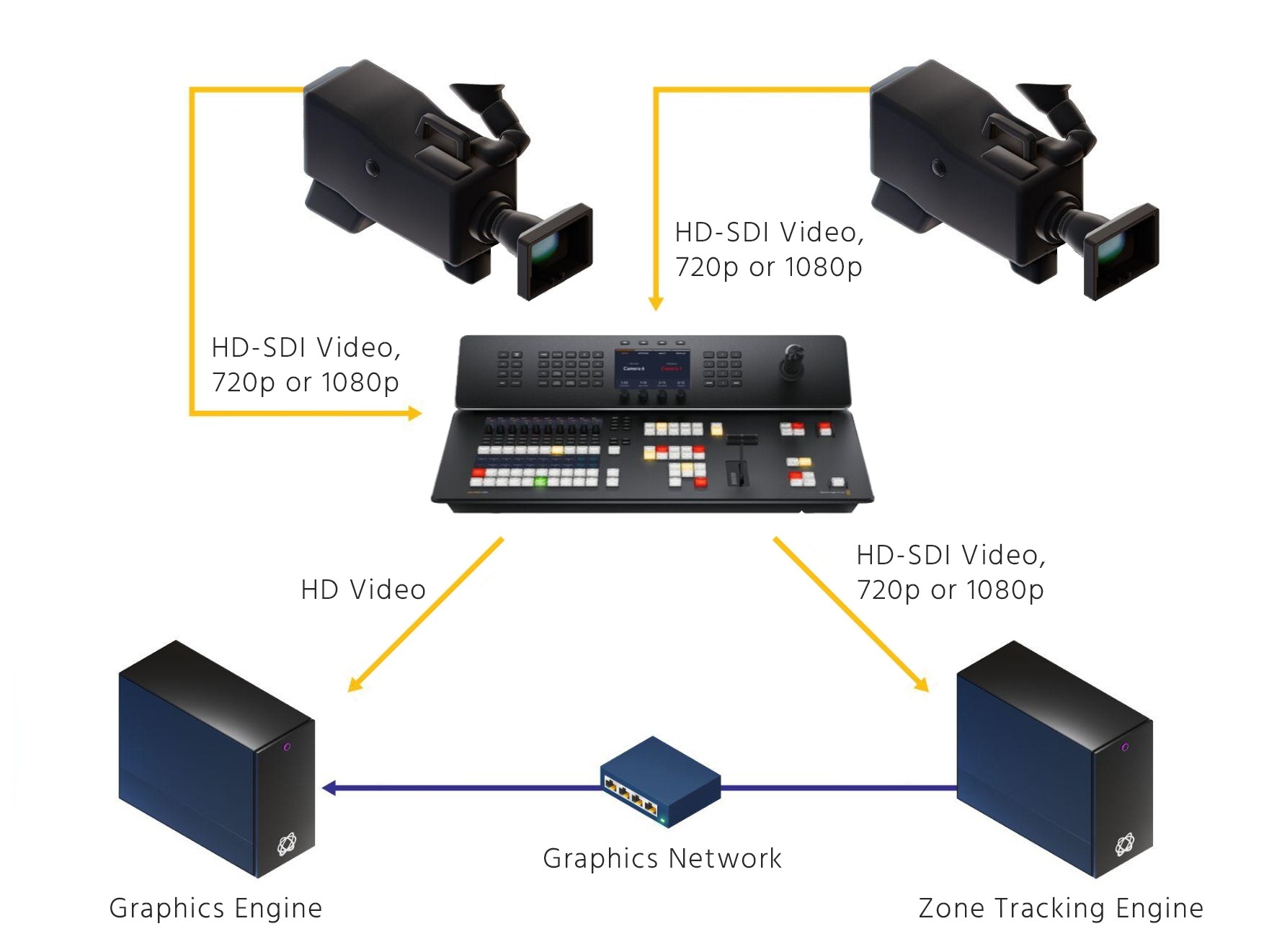
3.1 Hardware Setup
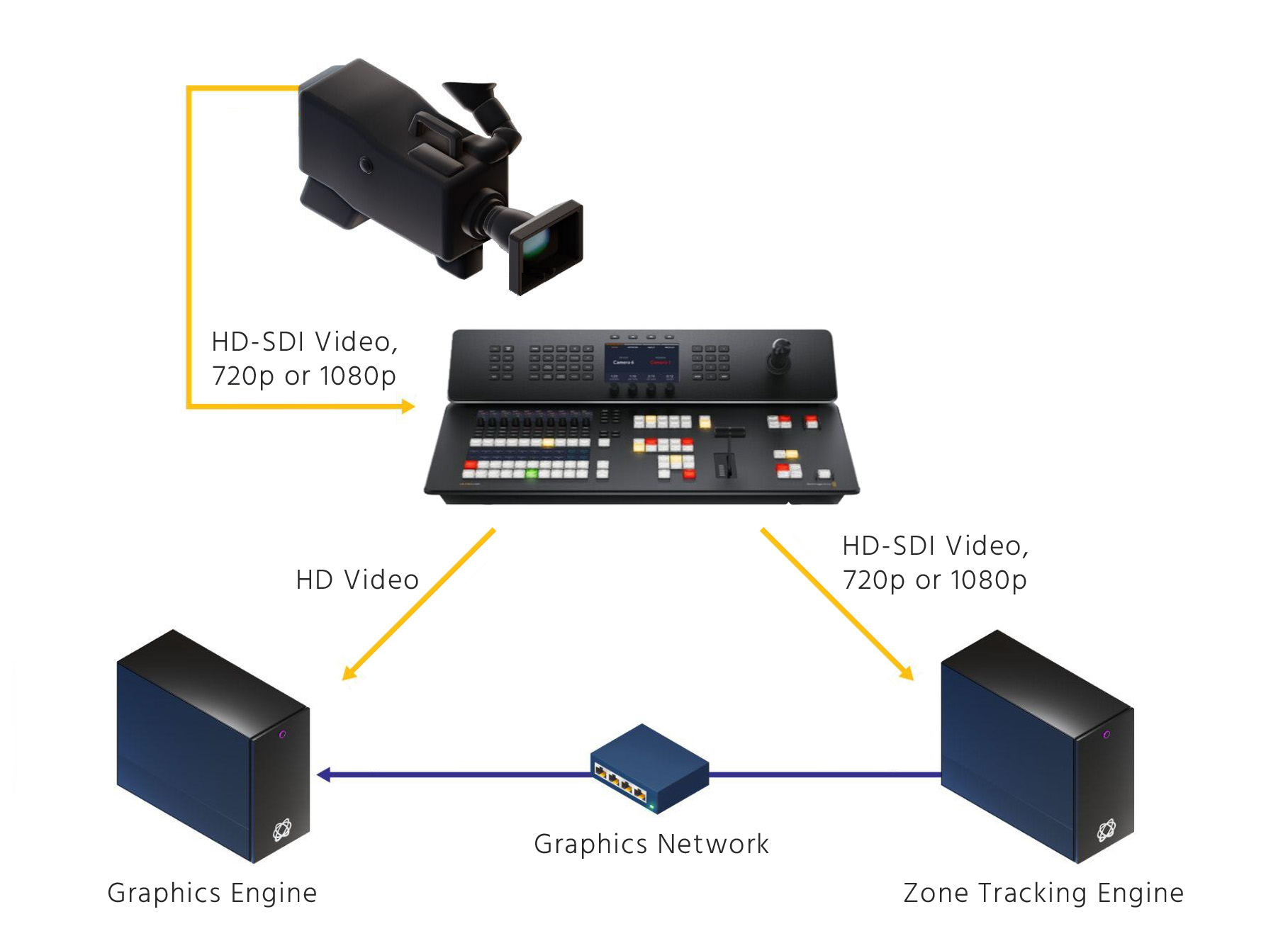
Multi camera on one Zone Workstation (consecutive operation):
For switching between cameras, switch video routing first and then Zone configuration. Switching between Zone configurations takes approx. 20 seconds. The camera which is switched to needs to show the playing field to allow re-initialization of the tracking.
3.2 Software Setup
For the operating system installation, please follow the respective manual or watch the video tutorial.
For the Zone software installation, please select the pxtrk-Zone software package. A description can be found in chapter 4.2 of the operating system manual or in the video tutorial.
4 Operation
Start the software in the task bar from Tracking → Pixotope Zone → Pixotope Zone
4.1 Start Screen
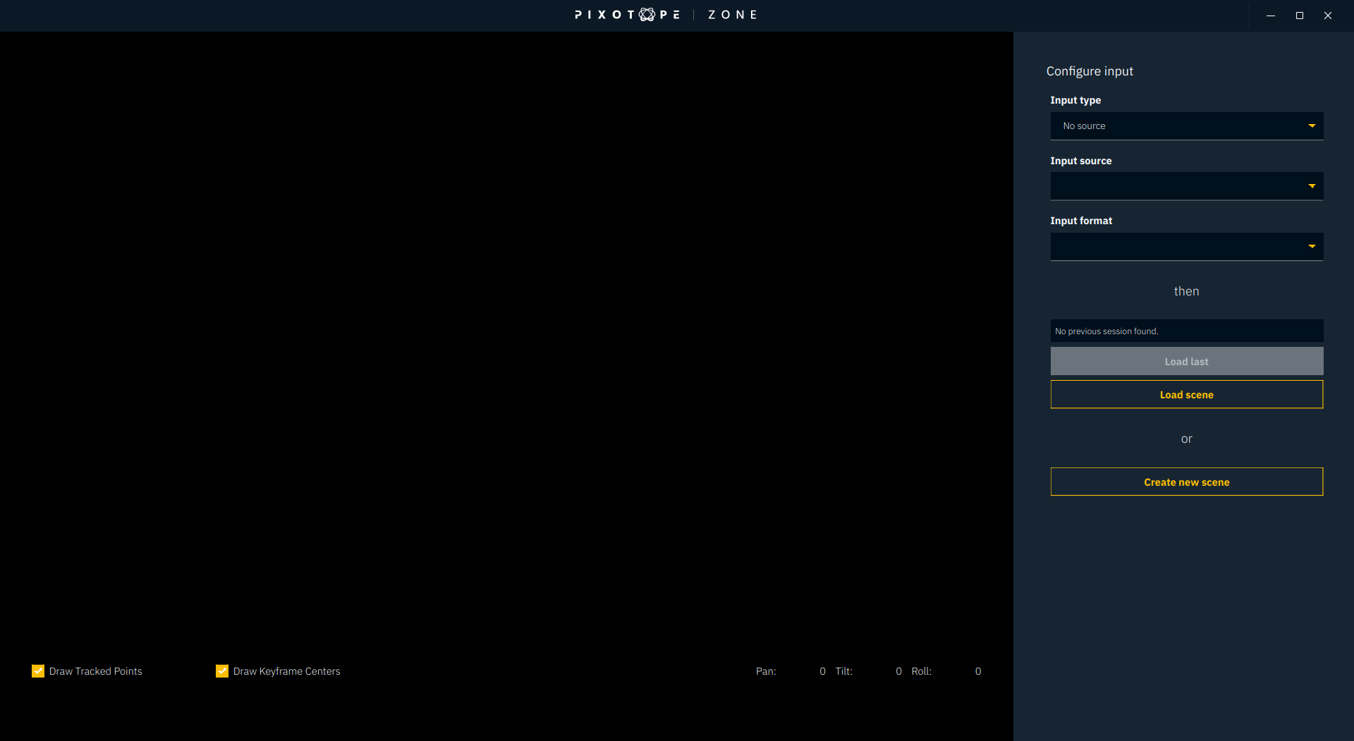
The start screen of Zone is where the video input source is set up. Currently only Blackmagic cards are compatible. Set the video input format in accordance with your true video signal. When the setting matches to the input source, the video will appear on the left side.
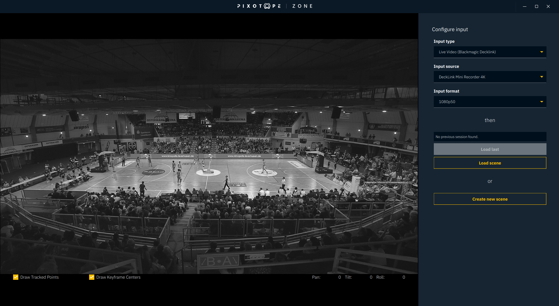
If a calibration had already been done before, the last used project will automatically be loaded after a 5 second timer. To stop this timer you can click on any of the 3 settings at the top.
Under Load scene you can load a project. Projects can contain multiple Checkpoints. Checkpoints are different states of the scan of the environment. So for example this can be an initial scan without an alignment or a full scan with alignment.
The default folder where the projects are saved is /home/tracking/zone.
Create new scene will enable you to start the setup from scratch.
4.2 System Configuration
There are three easy and consequtive steps to configure the system from scratch.
-
Configure
-
Initial scan
-
Align and track
After clicking on Create new scene you will find yourself at the first step which is called Configure. This is where you select the lens file.
4.2.1 Configure
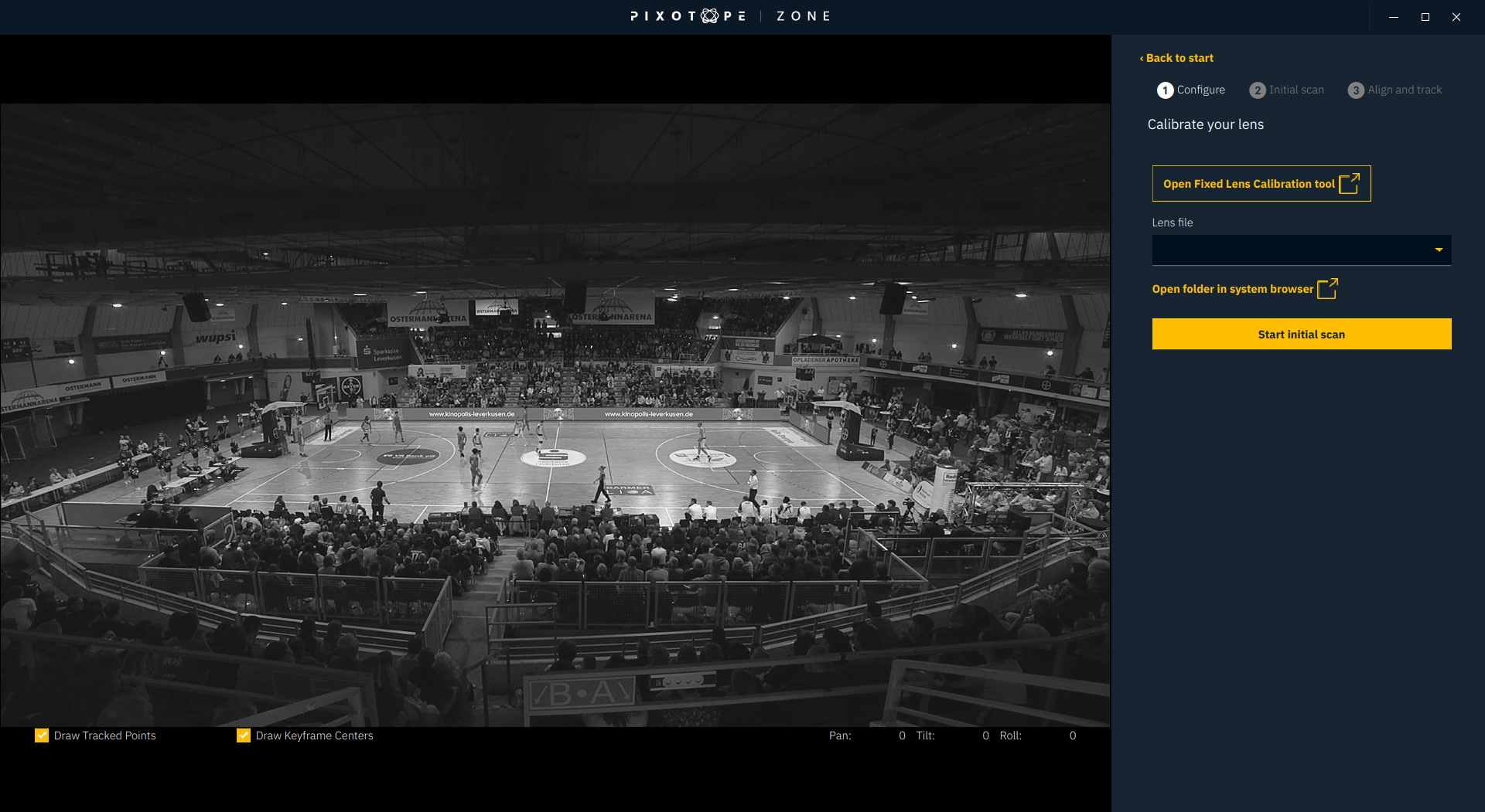
If the lens file hasn’t been created yet, you can start the Fixed Lens Calibration software from here. The video source will then be redistributed to the lens calibration tool for as long as it is opened.
The lens file to be used for Zone Tacking must be created with the Fixed Lens Calibration tool opened from within Zone. It cannot be created with the tool that is started from the AppManager or from the task bar.
Even when using zoom, only a fixed lens calibration is needed. It is recommended to create the lens file at the widest angle and with focus to infinity and auto-focus turned off. Since these positions are the hard end-stop of the lens’ mechanics, they can always easily be set.
The optical stabilizer of the lens can be used. Having the stabilizer on or off demands a proper lens calibration file for each.
-
Select the correct lens file
-
If the lens file hasn’t been created yet open the Zone lens calibration tool
-
Set the lens to its widest angle, the focus to infinity and turn auto-focus off
-
Create a fixed lens calibration file with the Pixotope calibration target. Refer to the general fixed lens calibration manual or the video tutorial.
-
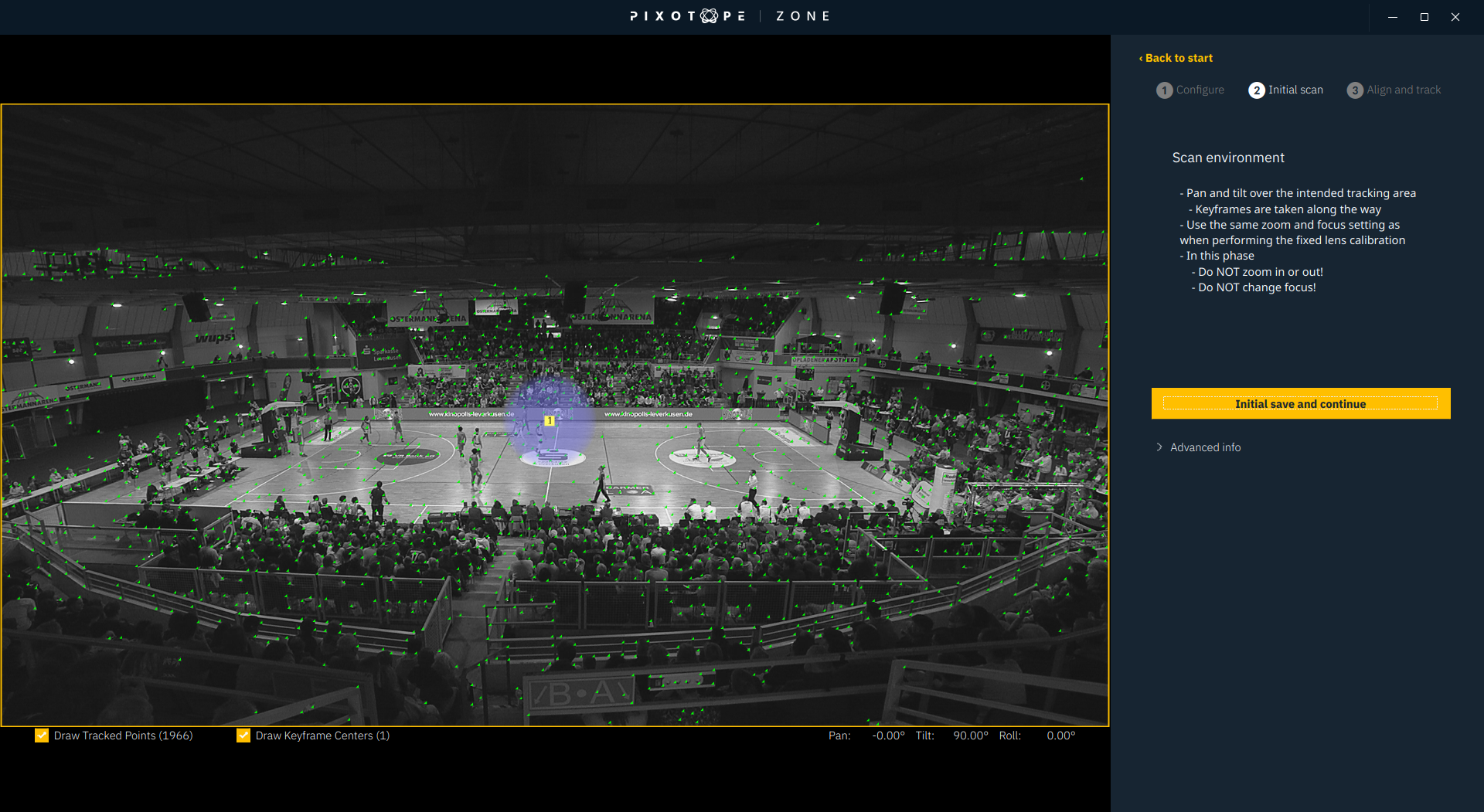
4.2.2 Initial scan
The goal of the initial scan is to scan the playing field in wide angle in the main filming direction. Approximately 5 to 10 keyframes should be captured, e.g. a simple pan movement will do the trick already. For an easy operation it is recommended to have at least one keyframe captured with the full playing field in view. If the field of view is not wide enough to show the complete playing field, it is possible to capture a keyframe with the 2 outside corners and 2 middle line corners only.
In any case a minimum of 4 points need to be in one keyframe.
The closer the environment looks to the live on-air situation the better, but this is not totally necessary if there are enough visual details that remain on their position like the logos on the playing field.
The program takes keyframes automatically when it is pointing at a new area of the environment (a minimum of 5 degrees difference in pan or tilt direction compared to the previous keyframe) or at the same area but at a different zoom level.
-
Make sure the lens is set to its widest angle, the focus to infinity and turn auto-focus off. Zoom and Focus must not change during the initial scan
-
Point the camera to the center of the field to have the entire field in frame
-
Click Start Initial scan
After clicking this button the software will immediately and automatically take keyframes to scan the environment. So only do click it if the camera is ready for the Initial scan.
-
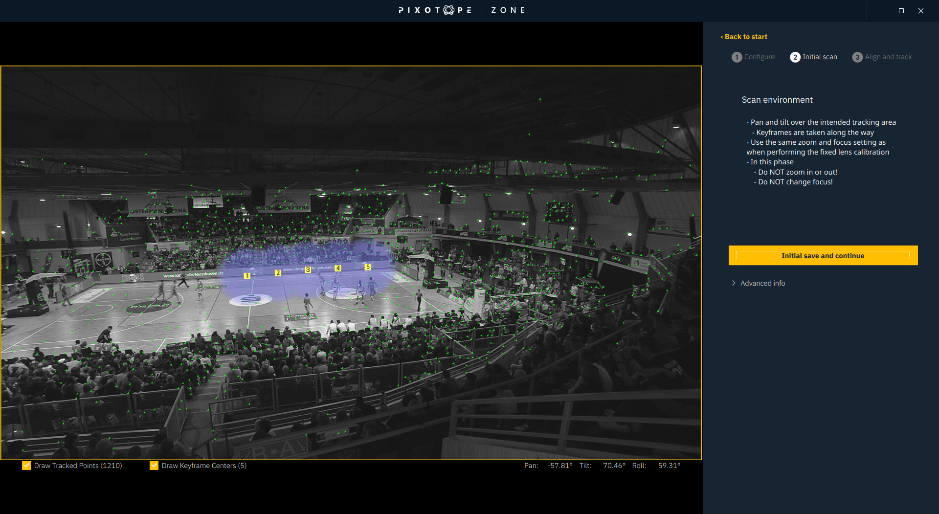
Perform a slow pan movement either
-
starting with the entire field in view
-
or from one side to the other, passing a point where the entire field is in frame
-
-
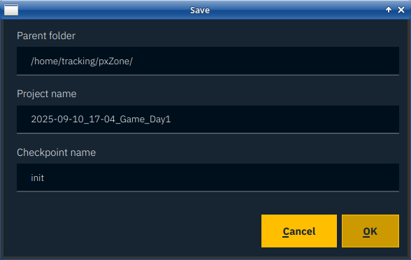
When this is done, click Initial save and continue. You will now be able to choose the name of this Checkpoint. Usually something with “initial”, as this indicates that it is the initial scan
4.2.3 Align and track
The optimal workflow is to do the alignment after the inital scan and then, after the alignment has been done, scan the rest of the environment. This is instead of scanning the entire environment first and then doing the alignment.
The reason for this workflow is that doing so provides a quick visual feedback already after the initial scan, to tell us if the setup will work. It also allows to send tracking data to the graphics engine earlier.
In the Align and track tab the system will continue to automatically take new keyframes as long as Lock Scene is not activated.
The lens can now also change zoom and focus.
-
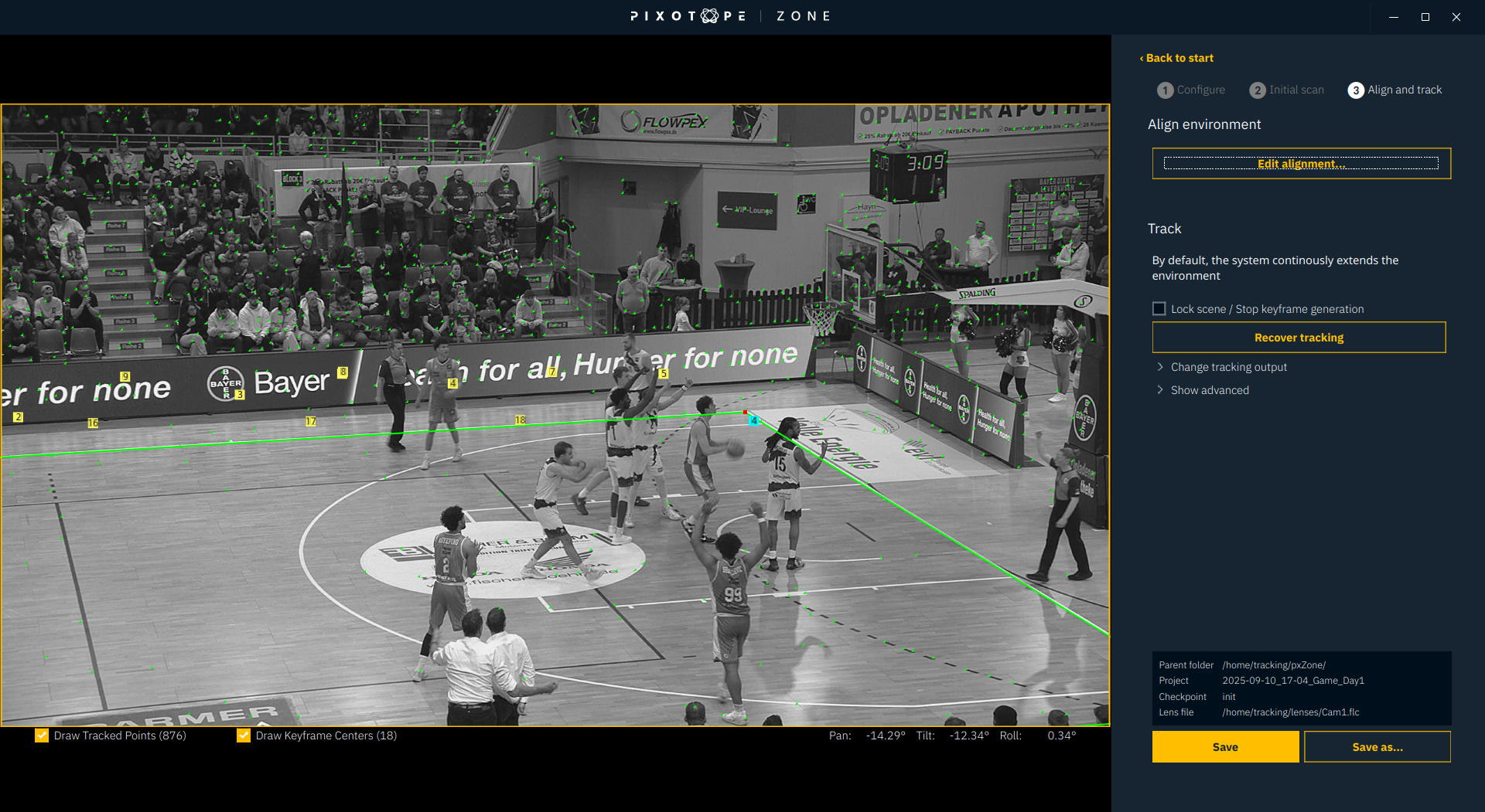
Click on Align…
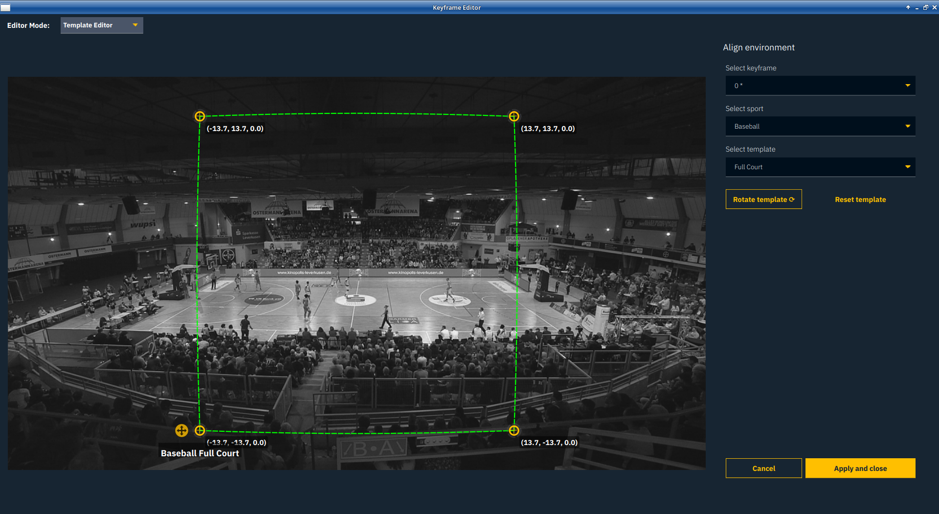
-
Select the correct sport
-
Select the correct alignment template that fits to your keyframes. If there is a keyframe with the entire field in view, choose Full Court
-
Select a keyframe that has at least 4 playing field corners in view
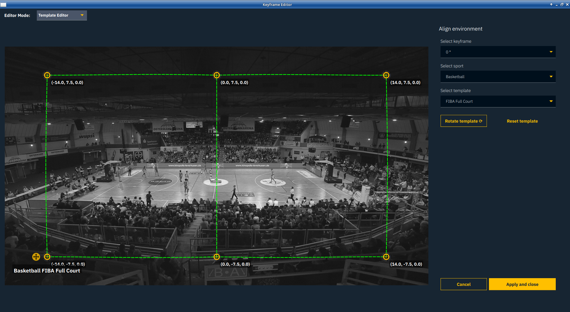
-
Use the yellow indicators to set the corners to the right position. The green lines help with the alignment, in case the corners are obstructed in the keyframe. The mouse wheel can be used to zoom into the keyframes.
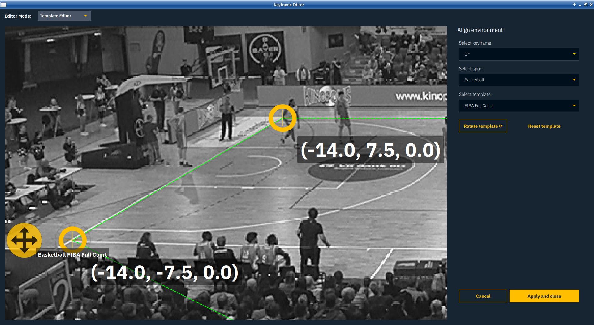
Each corner point is provided with the X, Y and Z coordinates.
By default the origin point is the center point of the playing field. A right click on a point let’s you set that point as the origin point.
You can rotate the template with the dedicated button to enable different viewing angles for multi-camera angles. E.g. when you are looking with a second camera from the opposite side towards the same playing field it needs to be rotated by 180 degrees. Please make sure to align the same coordinates to the same points of the real playing field when using multiple cameras.

-
When finished, click Apply and close
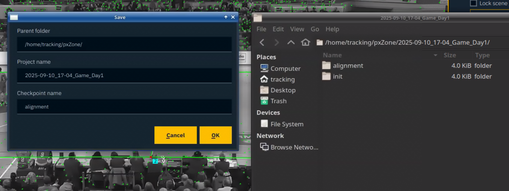
4.2.4 Final screen
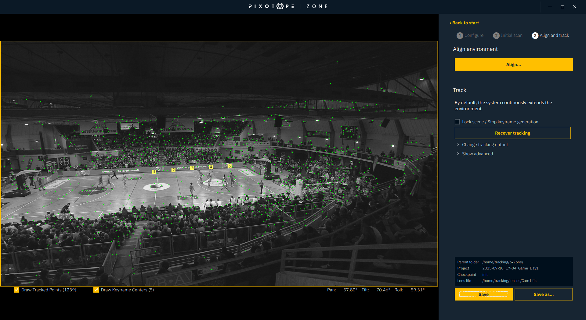
The tracked playing field grid will now be displayed on the live video, so the precision can be verified.
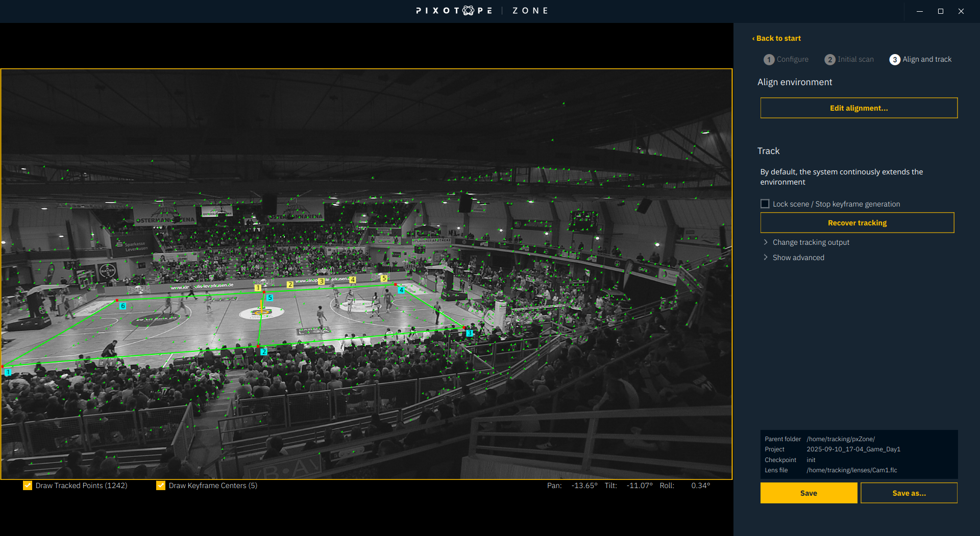
-
Click Save as… and choose a name for this checkpoint
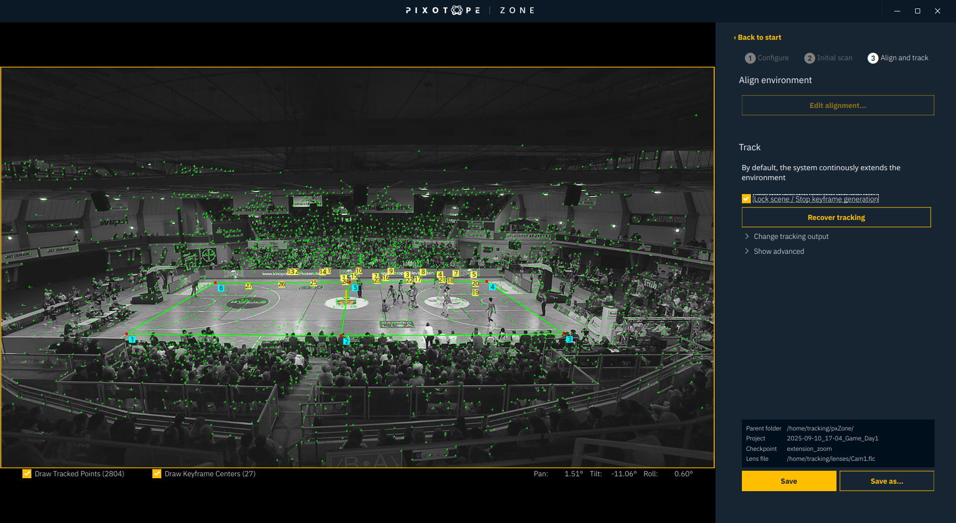
4.2.5 Extending
The scan can be extended in 2 ways:
-
by panning and tilting
-
by zooming
The goal should be to cover most perspectives and zoom settings of the camera during on-air time in advance.
-
Use pan, tilt and zoom to extend the scan
-
Save the extension into the active Checkpoint by clicking Save, or create a new Checkpoint in the Project by clicking Save as …
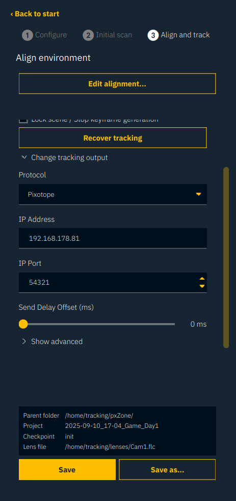
4.3 On-Air-Settings
4.3.1 Lock Scene
Lock Scene can be kept deactivated also during live on-air time, so that the environment can be extended at all times also during broadcasting.
Use Lock Scene when you expect the camera to show images outside the relevant tracking area or at unreasonable zoom levels! This prohibits to capture irrelevant or irritating key frames.
4.3.2 Recover Tracking
When Zone is loosing tracking it will always try to recover automatically. If it does recover but the result looks wrong, try to initialize the system manually by clicking Recover tracking.
Do not use Recover tracking on-air, as the system stops sending tracking data during the recovery time.
4.3.3 Sender and Delay
-
Click on Change tracking output to show the Sender settings for the tracking data
-
Type in IP and port of the graphics engine in the appropriate fields and select the Graphics engine vendor in the Protocol field
-
A delay within the frame can be added to the tracking data output with the Send Delay Offset slider. Additional delay can be added in the graphics engine.
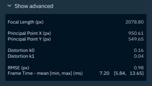
4.3.4 Show advanced
Under Show advanced more information about the curent calibration.
The Frame time needs to be significantly below the frame duration (about 16 ms for NTSC or 20 ms for PAL related systems).
The RMSE can indicate a bad lens calibration if it is unusually high. Usually it is below 1.0.
If you wish to receive a Pixotope Zone Demo from our team, please contact support@pixotope.com.
Sample footage for testing and the corresponding lens file can be downloaded here.