1 Preface
Compared to a studio installation of a camera tracking system, a Fly tracking system allows precise 3D real time camera tracking without additional hardware on the camera. The setup is very easy and fast. This is possible because the tracking is solely relying on the video stream of the filming camera.
For a system that is already set up and meets all requirements start from chapter 4.
For the Fly zoom feature go to chapter 5.
Sample footage along with the corresponding lens file for testing Pixotope Fly and Fly Zoom can be found here.
1.2 Working Principle
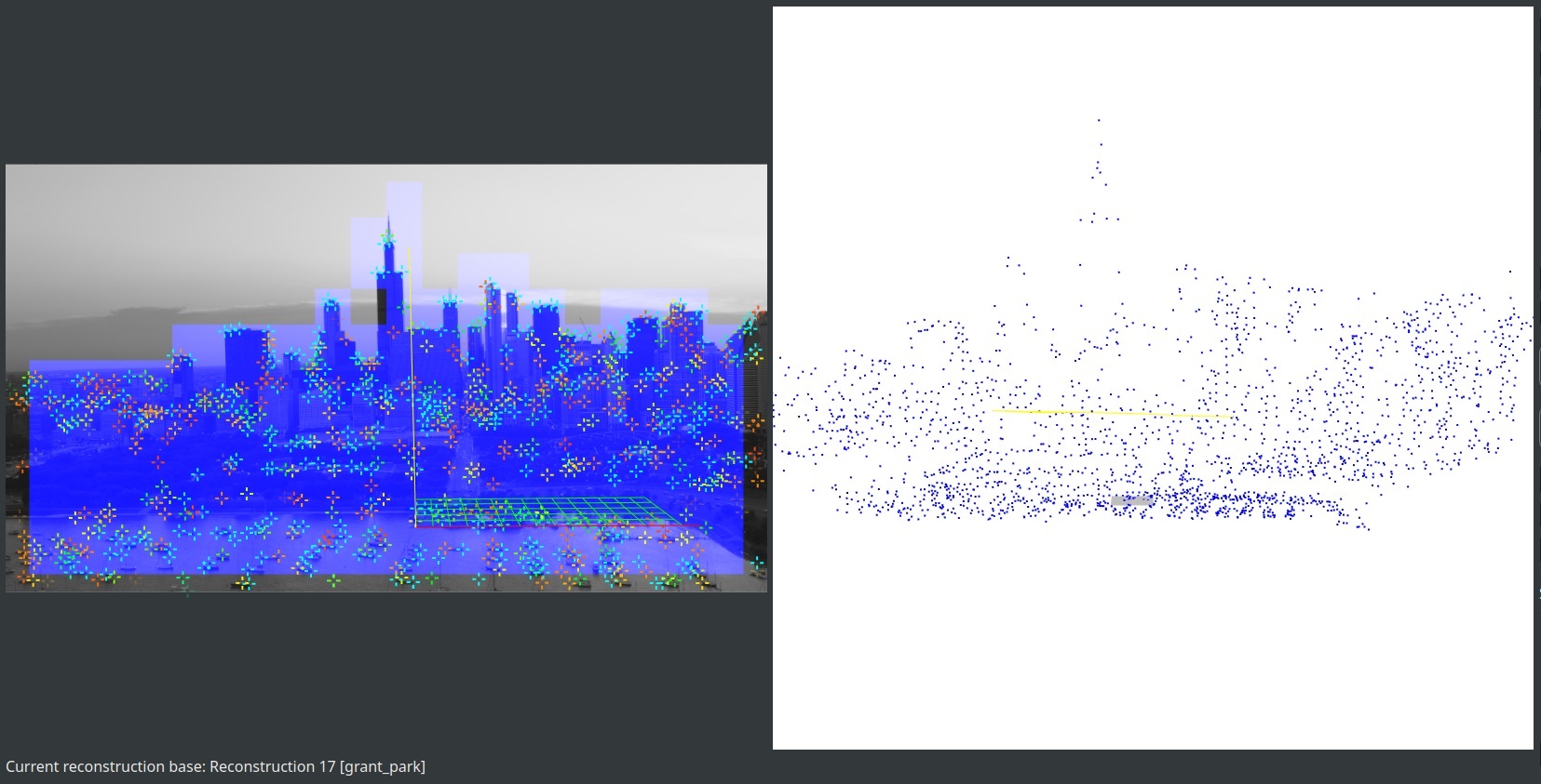
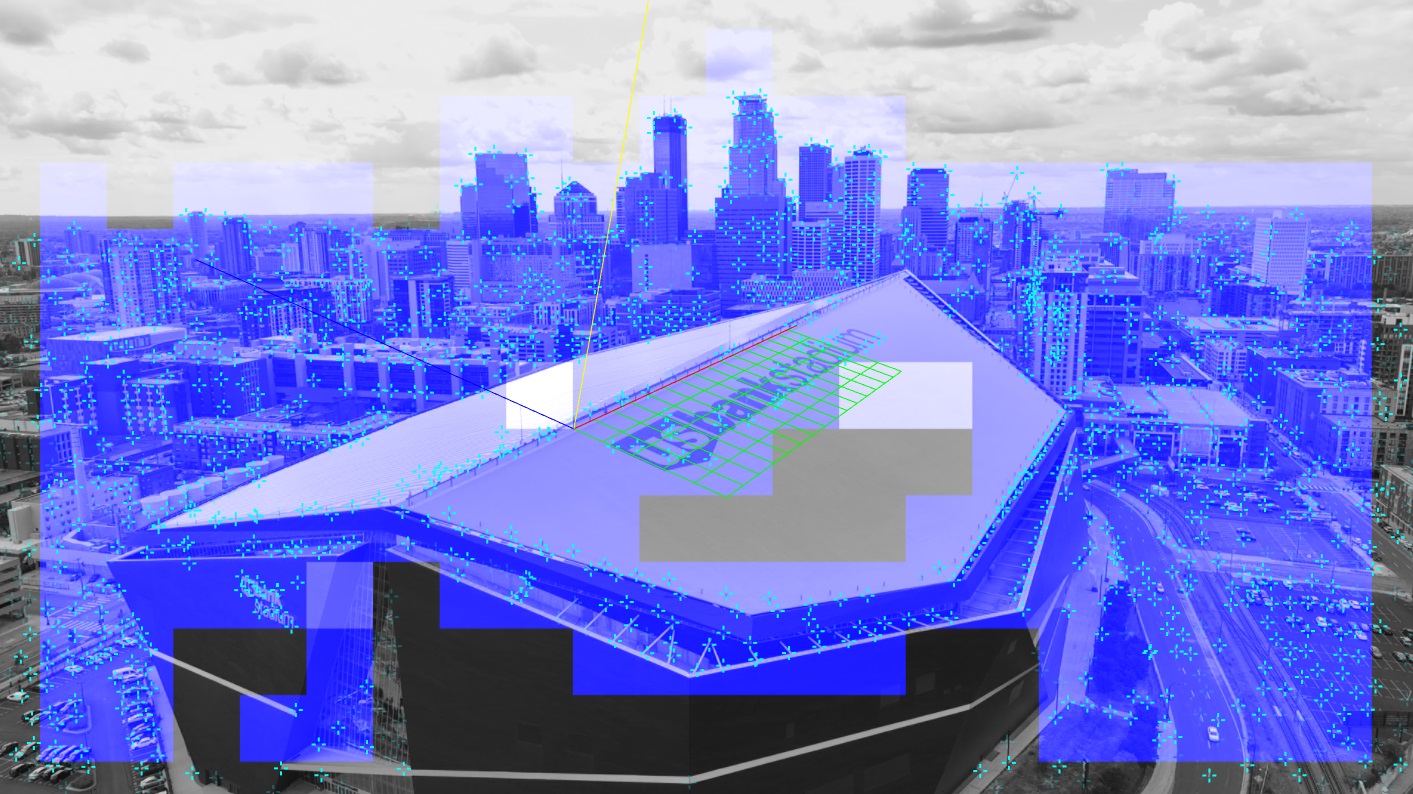
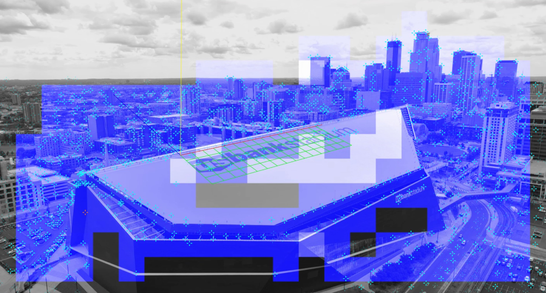
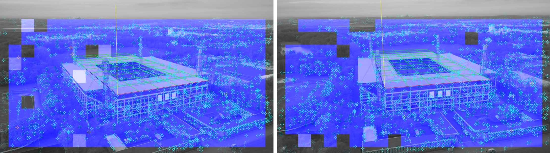
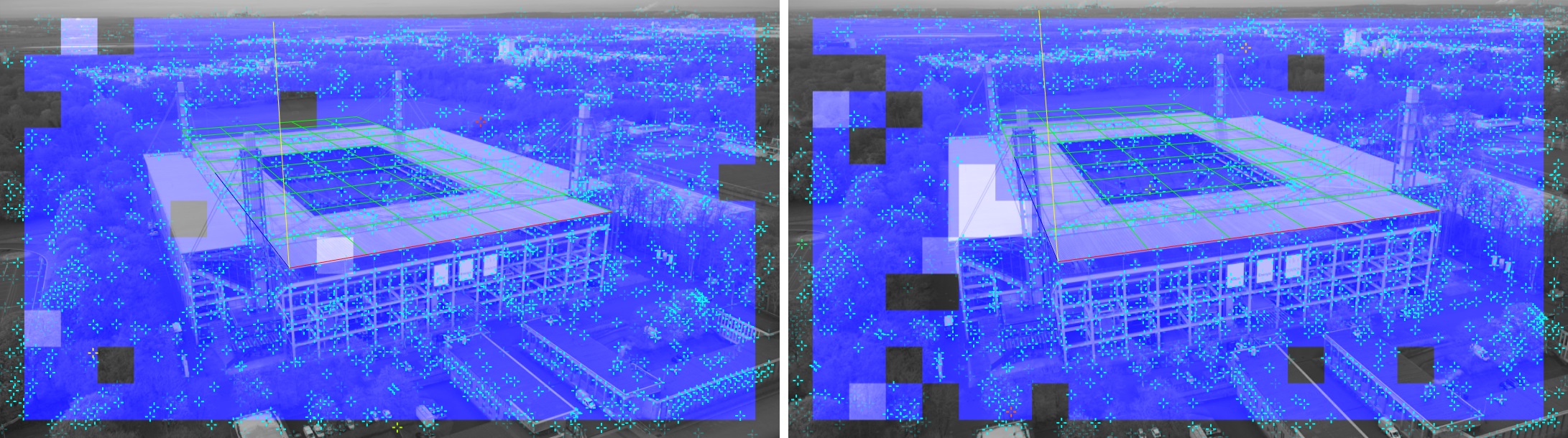
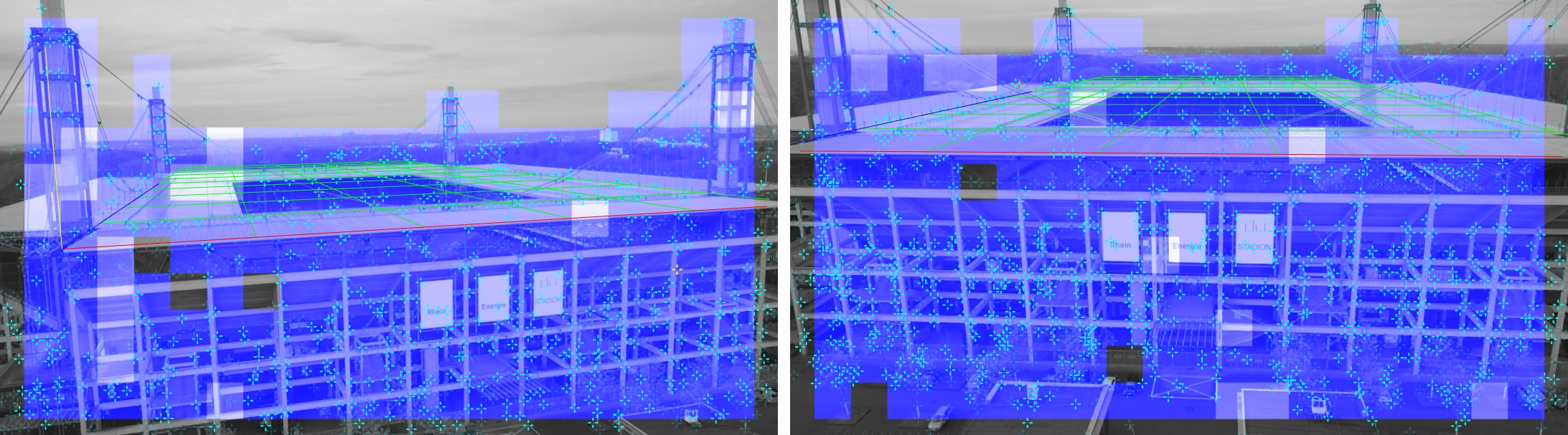
The tracking software uses solely video for reference. When scanning the environment, a 3D point cloud will be created based on well recognizable points in the video. These points are called feature points, indicated by little blue crosses in the video. The orientation of the coordinate system and also the scale will be defined manually by simple selections in the footage. This data is saved as a reconstruction. When a reconstruction is loaded, recognized areas are indicated by blue squares in the video. These squares show that tracking data is being generated and forwarded to the Chief.
The image processing detects high contrast corners. This means that lines, featureless and low-contrast areas do not contribute to the reconstruction.
The camera always has to be able to see a minimum of feature points. In drone applications this means that the drone can often (for example in stadiums) not look straight down, because the grass and marks on the grass alone don’t provide enough stable feature points. The contrast between white lines and grass is often not sufficiently high which reinforces this effect.
Some fixed objects like buildings or tribunes have to be inside the frame at all times!
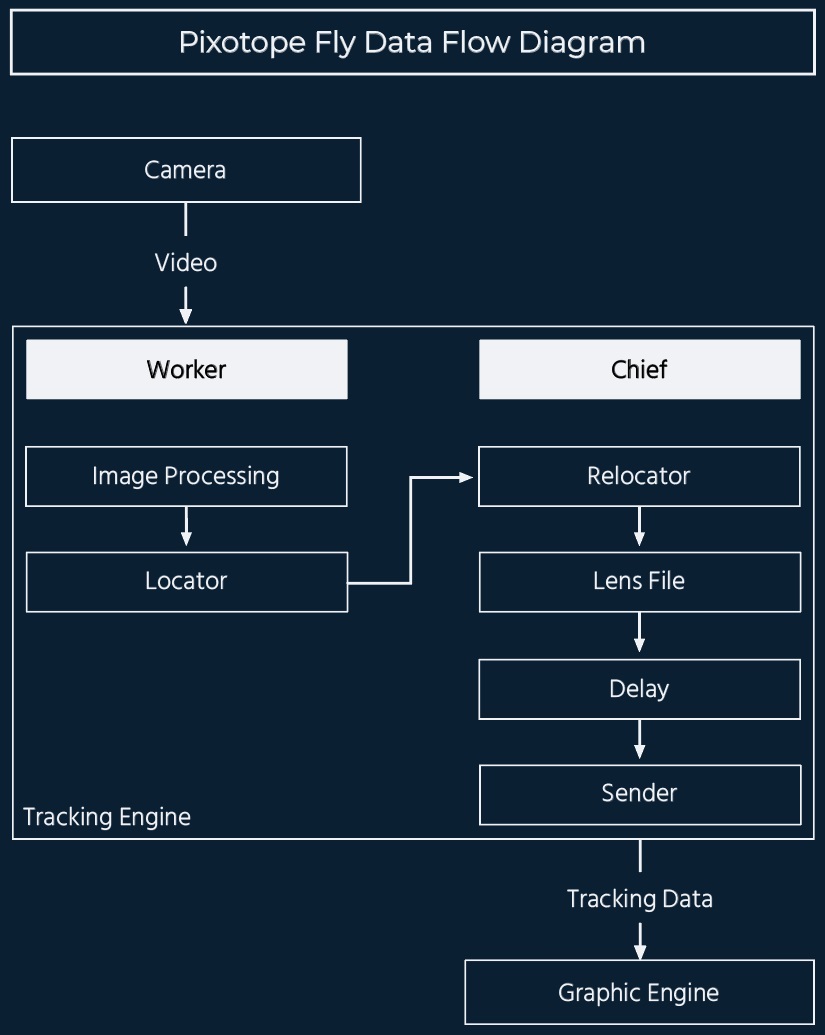
Pixotope Fly will use the Worker and Chief programs like any other Pixotope Tracking version. The Worker performs the image processing to calculate the pose of the camera. The Chief completes these data and handles the sending.
There are however some differences to other Pixotope Tracking versions:
-
The Worker uses the video of the aerial camera instead of a sensor camera
-
There is no connection to the lens, therefore a fixed lens setup must be used. The zoom feature is also solely based on image processing
-
No additional hardware like IMU or IR lights are being used
-
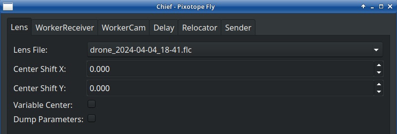
The Chief window is stripped-down, because many settings are not needed for Fly
-
The Chief does not need a video input. The incoming video is only required by the Worker
2 Technical Requirements
2.1 Hardware requirements
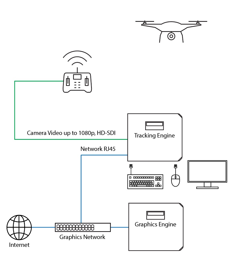
For the workstation please read the general Pixotope Tracking Engine Requirements. For Fly only 1 Gbit network port and only 3 USB ports are needed in the tracking engine. Other specifications remain the same.
Besides the tracking workstation the only hardware needed is the Pixotope calibration board. It is only needed to create the lens calibration file. This can be done beforehand as soon as the drone that will be used for the production is available. It can also be done on location, since it is a process of only a few minutes.
2.2 Video requirements
The video signal being used needs to be progressive. Interlacing the video frames undermines the image processing. Possible formats are 720p and 1080p. These can be downconverted from UHD format. Upconverting an interlaced video to progressive will contain interlacing artefacts that will disrupt the corner detection.
2.3 Camera requirements
A fast shutter speed is necessary for reliable tracking. A shutter speed that is too slow results in motion blur in the video during fast movements of the camera. Since the tracking is solely relying on the video signal, motion blur should be avoided by keeping the shutter speed preferably at 1/250s or higher.
Digital image stabilization that changes the used area of the image dynamically is not usable because such a mode makes it impossible to capture the lens distortion correctly. However, an image stabilization that crops the image by a fixed factor is possible to use. For using it the lens file has to be made with this image stabilizer being active. Please keep in mind that a digital image stabilization increases the video delay.
2.4 Lens requirements
The requirements to the lens depend on if the zoom feature will be used or not. Pixotope Fly uses in both cases the same fixed lens calibration.
Without the zoom feature it is necessary that during operation zoom and focus are not changed and auto-focus is off. A sufficient amount of feature points must be inside the video frame at all times during on-air mode to ensure a reliable tracking. This fact makes a wide angle lens much more capable.
With the zoom feature an additional reconstruction procedure is necessary. This is described in chapter 5. This procedure ensures that even when zooming in, a sufficient amount of feature points inside the frame is guaranteed. During any form of reconstruction it is still mandatory that no zoom, focus or auto-focus are being used.
3 Setup
3.1 Hardware Setup
3.2 Software Setup
For the operating system installation, please follow the respective manual.
For the Fly software installation, please select the pxtrk-Fly software package as described chapter 4.2 of the operating system manual. Everything else that is needed will be selected automatically and installed with these packages.
3.3 Chief Setup
The Chief configuration for Fly is different to a studio application of Pixotope Tracking. The Chief settings are saved in the folder /home/tracking/pxFly/ in the file pxFlyChief.cfg.
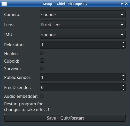
In order to configure the Chief for a Fly application follow the steps below:
If there is no Setup button in the Chief window, the Chief package has to be updated as described here.
-
Start the Chief
-
Click on the Setup button at the bottom of the Chief window
-
Configure according to Illustration 4
-
Choose as many Senders as you need for your setup
-
Click on Save + Quit/Restart
3.4 Worker Setup
The Worker settings are saved in the folder /home/tracking/pxFly/ in the file pxFlyWorker.cfg.
At the first start of the program the correct video source has to be selected:
-
Open the Settings in the Worker window and navigate to the Camera tab.
-
Select the Interface type.
-
Select the correct Device name, the Display mode and in case of a BlackMagic video card the correct Connection mode.
-
Click on Change image source.
-
If you already have the correct lens file, select it at Calibration file.
4 Operation
4.1 Lens Calibration
When using Pixotope Fly, the lens characteristics of the aerial camera being used have to be a known factor. This is necessary because the lens characteristics change the location of the feature points in the image. For creating an exact 3D point cloud which represents the reality, it is necessary that the lens characteristics are captured and saved before doing the reconstruction.
Create a fixed lens calibration file with the Pixotope calibration target for the Fly setup you are using. If you are not familiar with this process, please refer to the general fixed lens calibration manual or the video tutorial.
Even when using the zoom feature, only a fixed lens calibration is needed. This lens file has to be made in the widest angle of the lens and with focus to infinity and auto-focus turned off.
In the Fly version, the same lens file has to be selected in both the Worker and the Chief window:
-
Select the lens file in the Worker Camera tab for image processing.
-
Select the same lens file in the Chief Lens tab as well, to send it’s parameters to the graphics engine.
4.2 Reconstruction
When a new reconstruction of an environment has to be made, the aerial camera needs to be in the air and able to move around to see the tracking area from different positions. Due to limited air time it can be helpful to record the reconstruction flight and input the playback into the tracking engine. That way there is more time to create the best possible reconstruction.
The correct lens file, suitable for the productions settings has to be loaded in the Worker. During reconstructions the lens must always be in its widest angle with focus to infinity and auto-focus turned off.
Below you will find a step-by-step guide for creating a reconstruction with an aerial camera. For more information on this topic, please read the general reconstruction manual in the Pixotope Tracking Help Center or the respective video tutorial.
The additional reconstruction procedure for the zoom feature is described in chapter 5.
Some specific attributes have to be considered when creating a reconstruction with an aerial camera, mostly due to the larger environment dimensions of the tracking area compared to a studio application, the absence of dedicated markers and the influence of weather conditions.
4.2.1 Learning the Environment
1. Fly with the aerial camera while it sees the area that will be used for tracking.
2. Take keyframes of the area from various positions
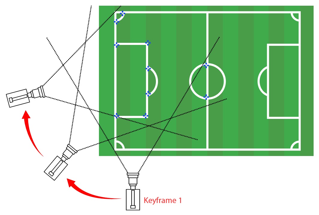
a. either by flying an arc (for example 90 degree) around a certain area
b. or by flying sideways.
Between two consecutive keyframes it is important that the drone flies with only little or no pan or tilt. The drone has to be at a different location in 3D space and pan or tilt should only change a bit. About two thirds of the area recorded in the previous keyframe should still be visible for the next keyframe after adjusting pan, tilt or position.
3. Take the first keyframe and let the aerial camera move to a different location without panning or tilting too much.
4. While still seeing most parts of what was visible in the first keyframe, but now from a different position, take the second keyframe.
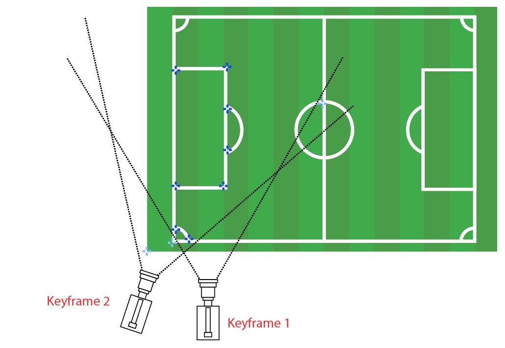
The initialization distance between the first two keyframes should be chosen according to the scale of the environment. In a studio half a meter distance between the camera position of keyframe 1 and keyframe 2 is recommended. A drone flying inside a stadium for example needs a larger positional difference between the first two keyframes. For example 5 meters or even more. If the distance is too high too many feature points get lost while moving.
5. Keep changing the position and perspective of the camera and take other keyframes.
6. Keep adding keyframes from different positions / perspectives until the entire area is reconstructed. After initializing the tracking with the first two keyframes Allow Extension can be used to have keyframes taken automatically.
Compared to a studio application the dimensions of the environment are larger when filming with an aerial camera. The feature points will have greater distances to each other and to the camera. Due to this fact the Distance factor in the Locator tab should in most cases be lowered. This will cause more keyframes being taken automatically, when Allow Extension is active. Values between 0.06 and 0.10 are good in most Fly applications.
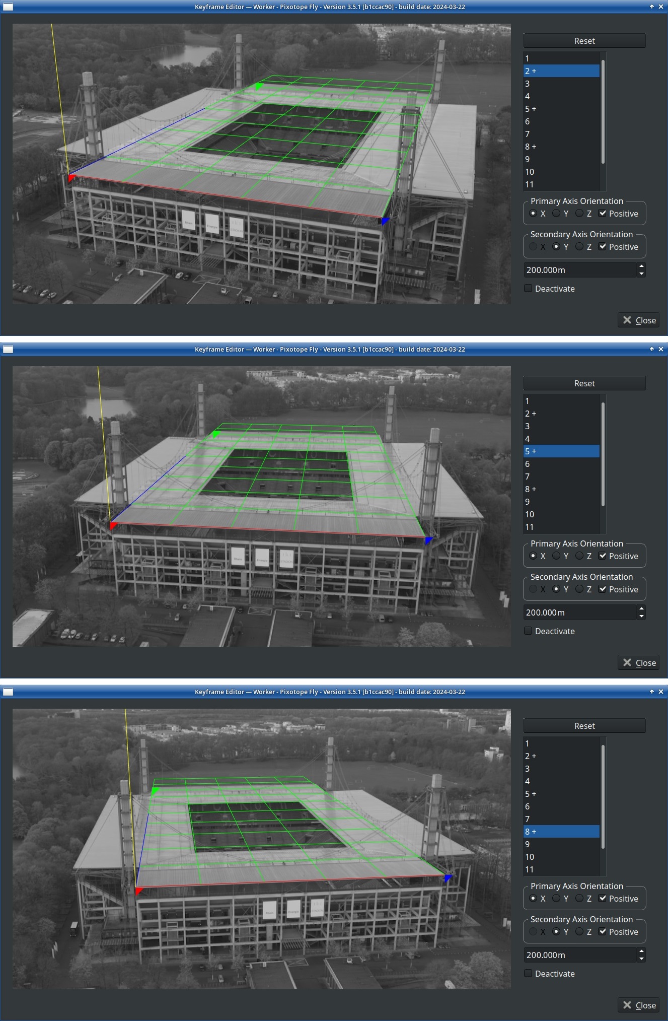
4.2.2 Setting transformation and scale
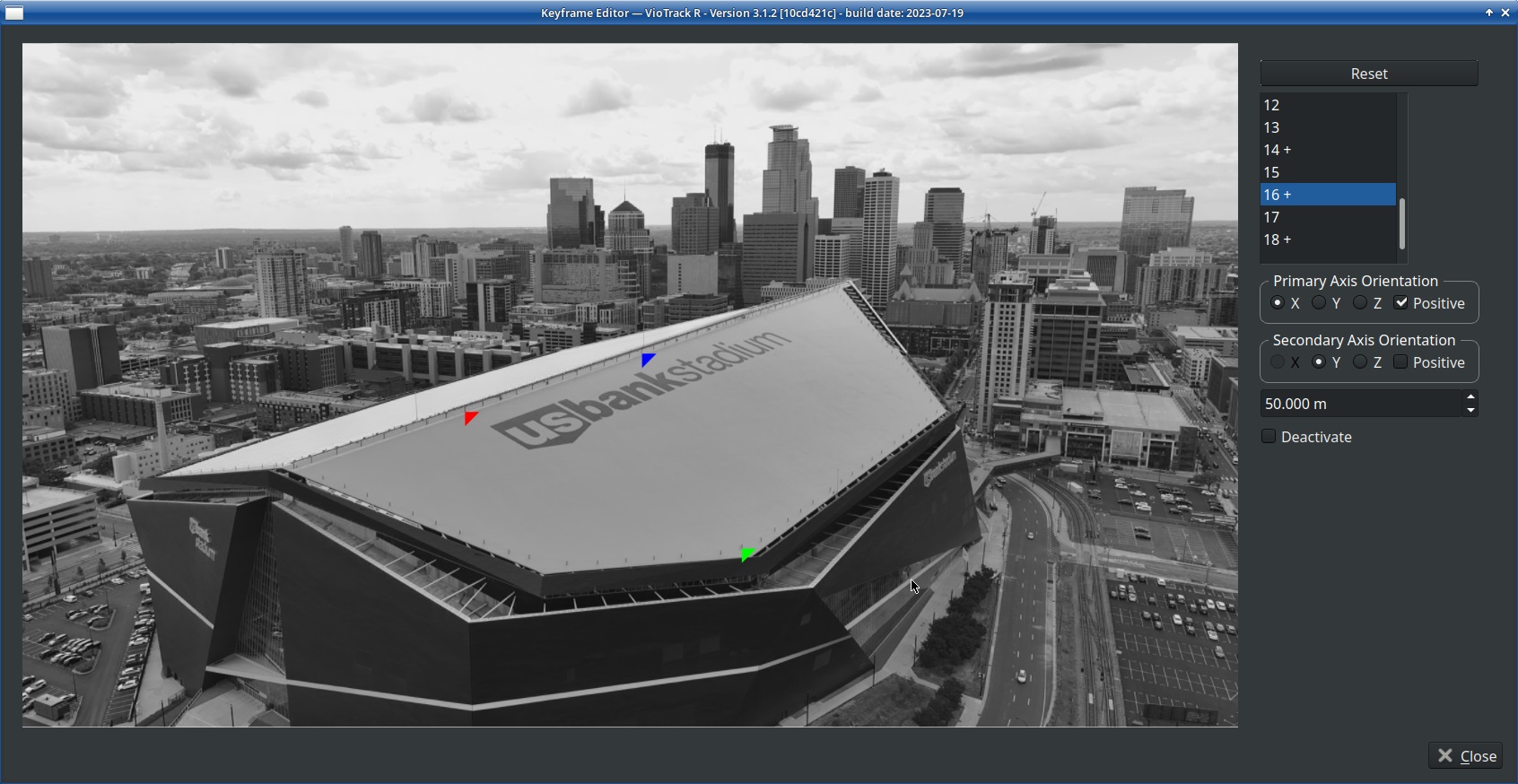
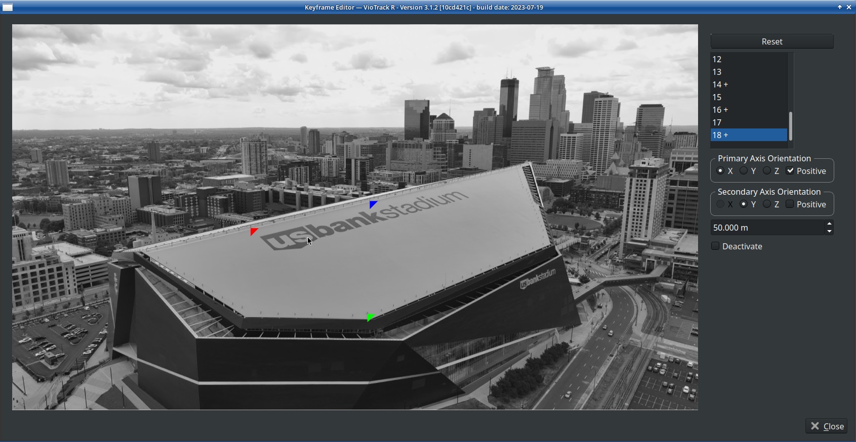
Choose three points inside the tracking area for defining the orientation and the scale. These 3 points must be on the same plane. This will create the zero plane, so ideally they should be on the floor. This is however not always possible (see example photos).
The three point have to be reconstructed from different perspectives and each one of them must be included in at least two keyframes. It does not matter which keyframes they are in.
-
Click on Set coordinates in the right side of the window or open the settings and click on Refine Coordinates in the Locator tab
-
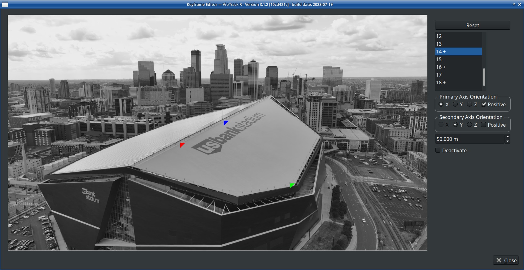
By clicking into the keyframe pictures the 3D position of the three points can be defined. Click on points from which the exact position can be easily identified:
-
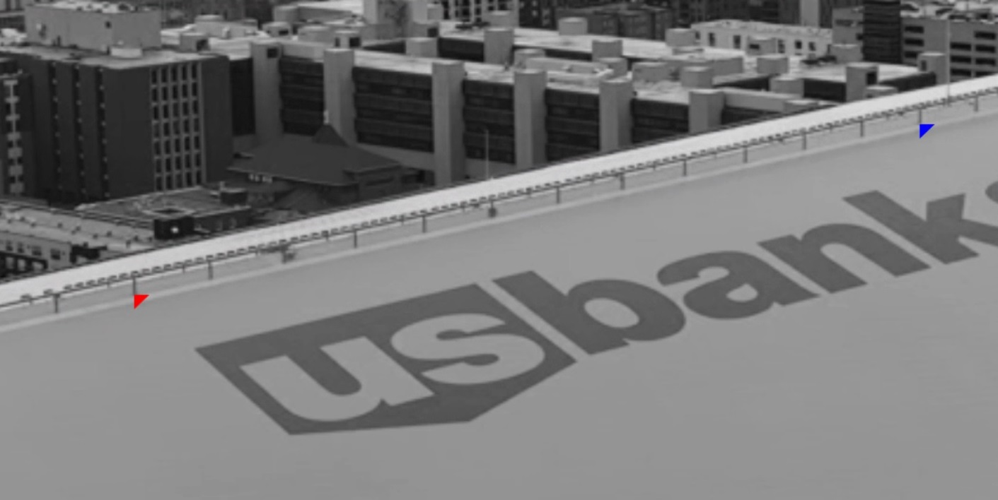
First click: the origin of the coordinate system (red triangle)
-
Second click: defines the primary axis from the origin to this point (blue triangle)
-
Third click: defines the direction of the secondary axis, depending on which side of the primary axis this point lies (green triangle)
-
-
Use the mouse wheel to zoom into the keyframes in order to have the triangle point to the location with high precision
-
Do the same thing in multiple keyframes. These keyframes must have a significant difference in perspective to one another. The position of each point has to be defined in at least two different keyframes
-
Increase the precision of the tracking
-
by refining the coordinates in more than two keyframes
-
by refining the coordinates in keyframes which have significant difference in camera position / perspective.
-
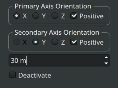
5. Define primary axis and secondary axis.
6. Define the scale by inserting the actual distance between the first two points in meters.
As in the previous chapter, the larger dimensions of the environment have to be considered when using an aerial camera. While in a studio it might be sufficient for the three coordinate points to have a distance of 2 meters to one another, this would not result in a good precision when tracking with a drone in a stadium. Larger distances between the points usually result in a greater precision of the tracking. In a stadium for example the corners of the outer lines of the field might be a good option. This would also have the benefit of making the determination of the correct scale easy.
7. Control the precision by checking the resulting grid. The red line indicates the X-axis, the blue line the Y-axis and the yellow line the Z-axis.
8. Close the settings window and click on Save Reconstruction to save the point cloud together with the refined coordinates in one new Reconstruction. The Save Reconstruction button will always save the current point cloud and its transformation into a new Reconstruction, so an already existing Reconstruction will never be overwritten.
When using camera tracking outdoors it can make sense to create multiple reconstruction of the same area for different day times or for different lighting or weather situations. Day time and night time make for a big difference in the feature point detection but also the change between cloudy and sunny weather or the change of the direction of the sunlight between morning and afternoon require to have multiple reconstructions. Once they have been created and saved they can easily be switched by clicking on Load Reconstruction.
4.3 Setup after Reconstruction
4.3.1 Sender
As soon as there are blue areas in the Worker video, positional and orientational tracking data are being calculated and are available to be sent to the graphics engine. This is done in the Chief window in the Sender tab. The IP and the Port where the tracking data are wished to be sent to have to be defined with Host and Port. The Options for data format have to be selected depending on your graphic engine vendor.
In the Setup menu of the Chief window the amount of Senders can be chosen.
4.3.2 Graphic Engine
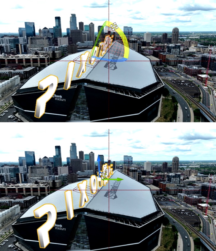
After the tracking data are being received in the graphic engine, create a 3D object and place it in the scene. In this example an angle and the location need to be adjusted in order to align the Logo with the building.
4.3.3 Delay
The tracking delay can be adjusted when the graphic engine can output a rendered image that contains a virtual object and the video. The delay setting is in the Chief window in the Delay tab. The value must not be set below 40ms. This is the minimum time needed for the software to calculate the tracking data.
The Send Delay which is used in other Pixotope Tracking is not necessary in the Fly mode, because it is mainly for synchronizing Chief and Worker video.
4.3.4 Smoothing
Fly uses solely the video to calculate the tracking data. Unlike the other camera tracking versions there is no additional motion sensor (IMU) being used. For stability and noise reduction it is therefore necessary to apply a smoothing filter to the tracking data. The Smoothing tab can be found in the Worker settings when activating Show Expert Settings.
-
Error tolerance defines the amount of smoothing applied. It should be between 0 and 0.03. The lower this value is the less smoothing is applied and the less negative effect it has on the delay.
-
Velocity update filters the acceleration to counter erratic movements. This setting will affect the tracking delay, so be aware that the video delay will have to be adjusted when applying Velocity update. It should be between 0.3 and 1 and preferably and as high as possible
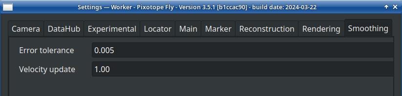
A smoothing filter can cause an effect similar to a wrong delay. To minimize this effect try setting the Velocity update to 1 and lowering the Error tolerance. Check with the graphic engines output to find the optimal values for the application.
A good reconstruction and lens file can allow the usage of only a minimal smoothing filter, for example an Error tolerance of 0.005 and a Velocity update of 1.00, or none at all (Error tolerance = 0.000.
4.3.5 Relocator
In the Relocator tab the position and orientation of the entire coordinate system as a whole can be changed. Type in positional values in meters. Pan, Tilt and Roll are considered in degrees and looking along the Y-axis. The Relocator applies when the Active check box is checked.
4.3.6 WorkerCam
This tab is used in other applications for the Offset between Chief and Worker camera. In Fly the values should be all 0. The Lens Delay can be ignored.
5 Fly Zoom
An additional reconstruction procedure can be made and added to the reconstruction that was created according to chapter 4.2. This procedure adds more detailed 3D information about a certain area. These detailed information then allow for the camera to zoom in on this exact area.
How far the camera can zoom in is determined by the amount of visual details in that area and the specific lens characteristics. By testing the zoom after the reconstruction procedure, the zoom-limit must be determined before going on-air.
The zoom feature is included in the newest Pixotope Fly release (version 3.5.1 or newer). No extra license is needed for it.
The zoom feature uses the same fixed lens file that is used for Pixotope Fly without zooming (chapter 4.1).
5.1 Reconstruction Procedure for Zoom Feature
Check out the video tutorial about Pixotope Fly Zoom.
The reconstruction procedure for zoom should be made after the general area has been reconstructed and it has been decided which area shall be zoomed in on. The drone then has to fly in a zig-zag path towards this area while its lens remains in the widest angle. This is due to the fact that keyframes can always only be taken while the lens is in the widest angle. As the drone is getting closer to the area, more detailed 3D information become visible and can therefore be added to the reconstruction by taking keyframes. This higher amount of detail in the target area is necessary when the lens is zooming in on it.
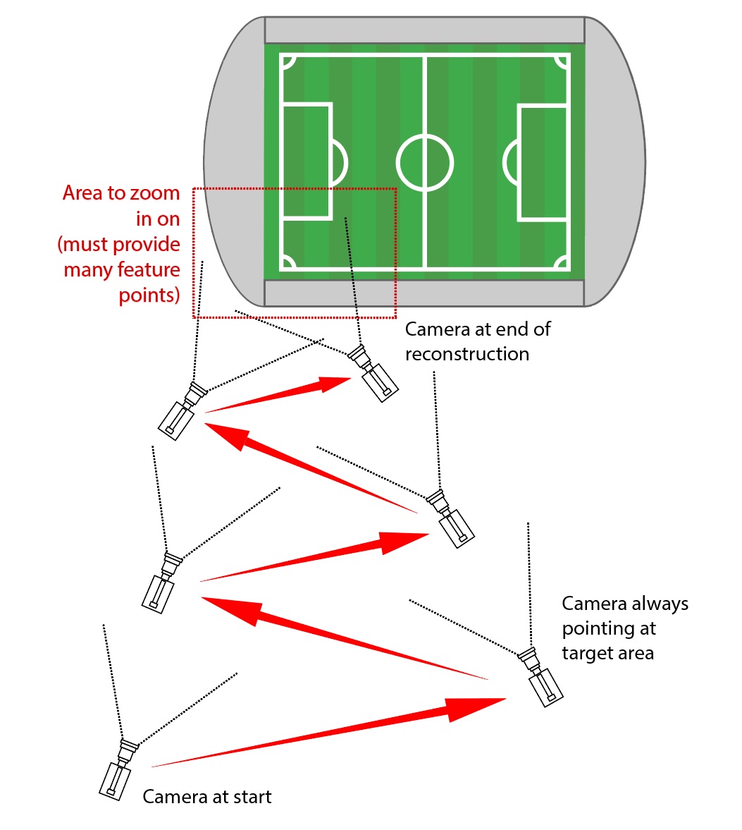
-
Reconstruct the general area (chapter 4.2)
-
Fly around taking keyframes
-
Set coordinates and scale
-
Save the reconstruction
-
-
Fly the zig-zag path towards the desired zoom area. In our example it’s the front part of the stadium. Take keyframes along the way
-
If necessary lower the distance factor or set keyframes manually
-
Make sure to take multiple keyframes each way you are flying. For example when flying from left to right, take multiple keyframes. Then when flying from right to left, now closer, take multiple keyframes again and so on
-
Make sure to also take keyframes at the outmost positions
-
-
When finished, enable TTL Zoom Mode and then save the reconstruction. Whether Enable TTL Zoom Mode is active or not active is saved with the reconstruction
-
Fly the drone back to the beginning position
-
Test the zoom
5.2 Enable TTL Zoom Mode
Zooming in with the camera in Pixotope Fly only works while Enable TTL Zoom Mode is active and after the reconstruction procedure has been done for the area to zoom in on. The TTL Zoom Mode causes the algorithm to detect zooms, calculate the distortion in real-time and adjust the feature point detection accordingly. Without this setting set to active, zooms would not be detected as such but rather be interpreted as the camera moving forward. There would also be no compensation for the variation of the lens distortion/parameters, which would cause the system to lose the feature points and eventually the tracking.
For these reasons TTL Zoom Mode must always be enabled as long as the camera does zooms.
As long as TTL Zoom Mode is active no keyframes can be taken. To add more keyframes, deactivate it and set the camera to the widest angle.
5.3 Reinitialize Tracking
If the tracking is off or looks wrong after zooming out, click the Reinitialize Tracking button. This button reloads the reconstruction and therefore can only be used while the lens is zoomed out. After a zoom-out, the tracking should be reinitialized before doing another zoom!
5.4 Sample Videos
6 Drone Operation
Some best practices for working with an aerial camera have been observed:
-
It should be explained to the drone pilot beforehand how he is supposed to fly to avoid problematic moves like sudden pans during reconstructions.
-
Direct voice connection with the drone operator is very helpful during the flight.
-
Keep in mind that the drone operator is most likely not seeing the tracking interface.
-
Stay ready to add keyframes manually. This might be needed in tricky areas, for example when flying close to a certain area or object.
-
Since the flight time of a drone is limited and productions can be busy it can make sense to record a video of a flight and play it back to the tracking engine to have more time for testing.