This panel is available when using an XR license
When adding a virtual set extension to an XR setup, matching the colors of the LED walls to the AR graphics manually is tedious. A variety of components in the video chain have an impact on the output colors
-
the XR render machine
-
the Display Processor for the LED wall
-
the LED wall itself
-
the on set lighting
-
the camera
-
the AR render machine
The Color matching panel does the whole calibration for you. Just follow the steps listed below.
What this calibration actually calibrates: we are not calibrating the LED wall itself. We are calibrating the LED wall, the LED processor and the camera (including how light bounces off the wall in the room) as one system, by measuring what the wall looks like through the camera. The resulting offset is applied to the AR set extension (and optionally to the wall output), so the set extension matches what the camera captures.
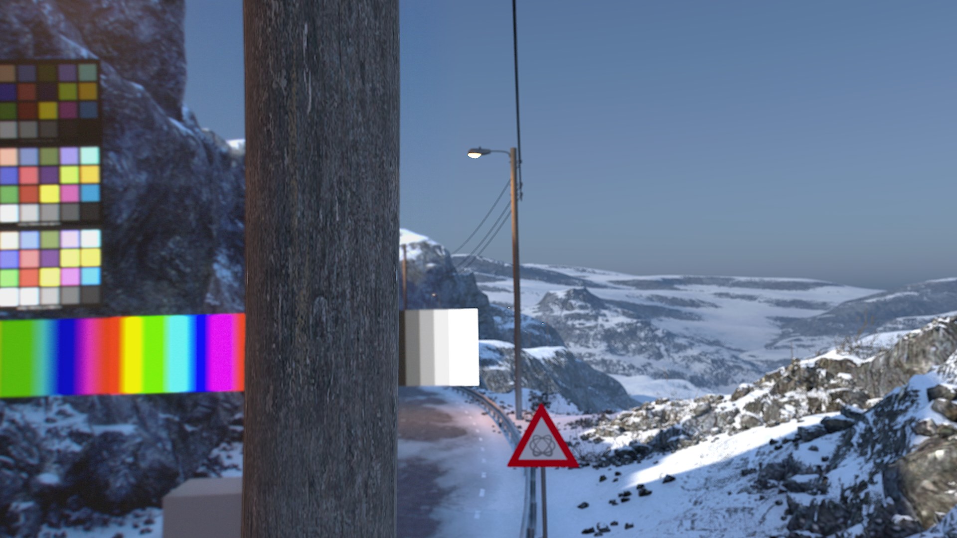
Example calibration done with 9 samples
|
|
LED wall |
Set extension |
|---|---|---|
|
No color matching Notice the visible seam in the middle |
|
|
|
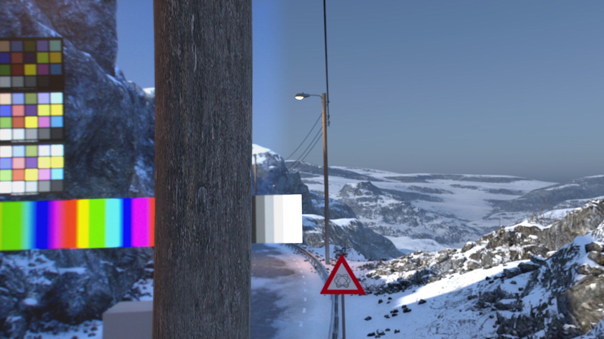
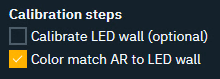
Color match AR to LED wall
This can be useful if you don’t want to change the look of the LED wall, but instead have the graphics adapt. Notice that the AR now inherits the blue shift from the wall. |
|
|
|
|
LED wall |
Set extension |
|
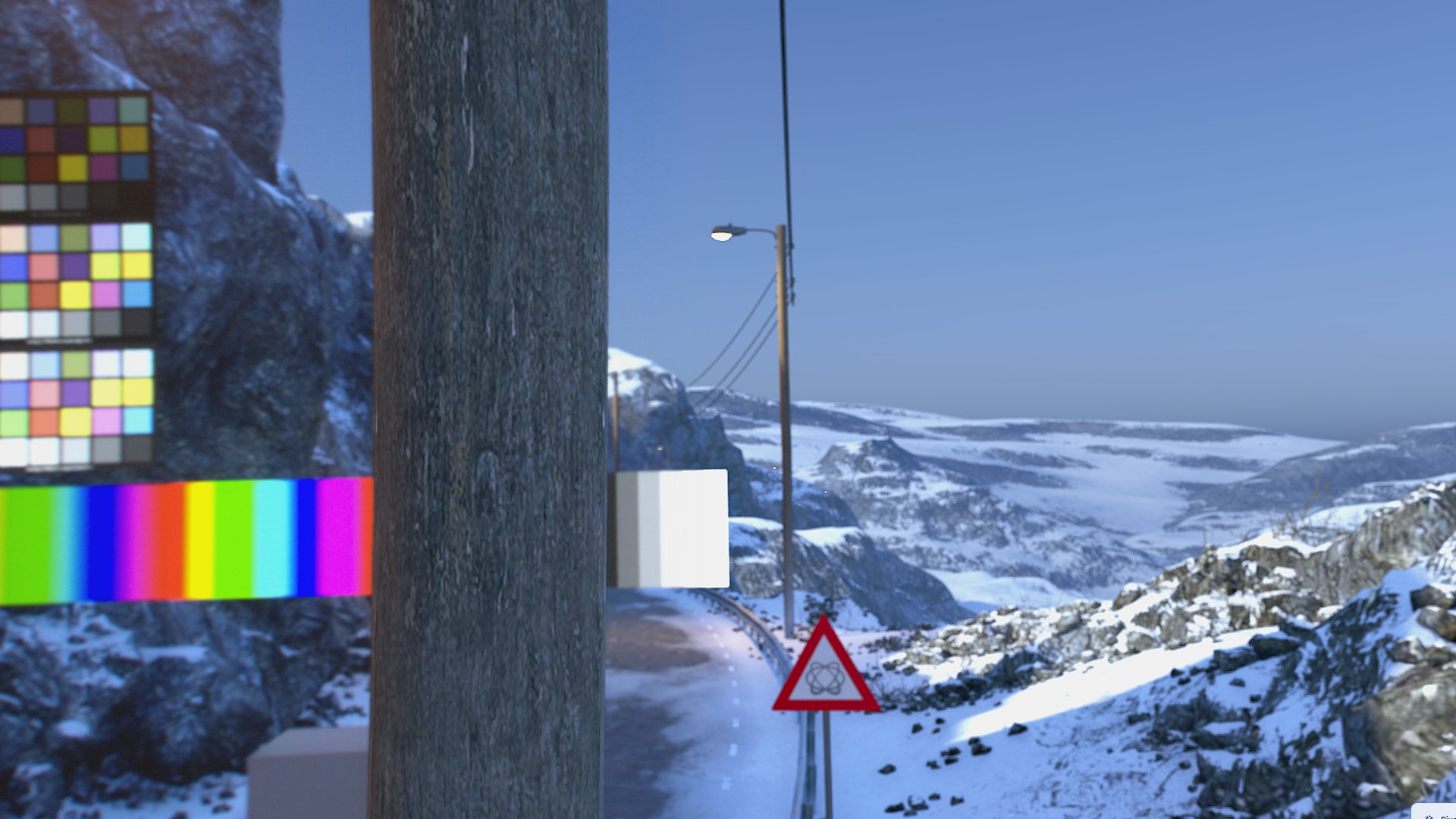
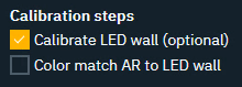
Calibrate LED wall
Notice how the LED wall is color corrected, but the AR still looks the same and is not gamut clamping. |
|
|
|
Both
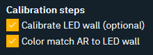
This is the best possible calibration which will color correct the wall and gamut clamp the AR. Notice the loss of intensity in the white color chart and show in the AR. |
|
|
|
|
LED wall |
Set extension |
Choosing color profiles for XR
The most important concept to understand: there is no connection between how you color manage the LED wall and how you color manage what the camera captures. From the camera's perspective, the LED wall is the real world - a physical object being filmed, just as if someone had painted the backdrop. You do not color manage the real world from the camera's point of view. The colorimetry of the wall and the colorimetry of the camera are completely distinct, and the profiles are chosen independently:
Output to the LED wall (XR machines)
-
Choose a format that takes full advantage of what the wall can do. Modern LED walls are HDR capable (often several thousand nits peak), so this typically means PQ or HLG - both use the Rec.2020 gamut
-
PQ is an absolute mapping: a given code value always corresponds to a specific amount of light (nits), which makes it possible to specify exactly how much light comes off the wall
-
HLG is a relative mapping: the maximum value maps to whatever maximum brightness the LED processor is configured for (typically 1000 nits)
-
Using as much of the wall's dynamic range as possible also lets you expose the camera lower, so the wall's darkest values can read as proper black through the camera even if they look grey in person
Camera input and set extension (AR machines)
-
The camera input profile is simply whatever the camera actually delivers (e.g.
Camera Rec.709,Rec.2100-HLG, a log format). The wall's output format plays no role in this choice -
The AR set extension uses the camera's profile - never the wall's. The set extension has to match what the camera captured, not what was sent to the wall
Display referred content (aux inputs) shown on the wall
When you bring a display referred source (e.g. a Rec.709 video feed or graphic) onto a Rec.2020/HDR wall, set its input profile to what the content actually is (e.g. Camera Rec.709), so it is linearized into the same scene referred world as the rest of the graphics. Remember that the wall is then filmed by a camera - content that looks correct in person will not automatically look correct through the camera. Color match the AR to the wall through the calibration below, and adjust the content as needed for the camera view.
Calibration
Prepare the following
For the calibration to be as accurate as possible make the following preparations to your
LED wall
-
Make sure the LED wall itself is properly calibrated before Pixotope enters the picture. Panels are normally factory calibrated (measured with a spectroradiometer), and the studio should verify the wall and processor are set up correctly - a grossly miscalibrated wall (e.g. with a strong color cast) is not something Pixotope's color matching is meant to fix
-
This should be part of the pre-install checklist / scope of work: the customer calibrates their studio (lighting, camera, wall) without Pixotope in the loop first, then Pixotope is fitted in and matched on top
Lighting
-
Set up production ready stage lighting
-
Set up production ready ambient lighting
Camera(s)
-
Disable automatic white balance
-
Disable dynamic aperture/exposure
-
Set accurate black/white balance
Frame
-
Aim the camera at the center of the LED wall
-
Zoom in so the camera frames only the LED wall
-
Lock off the camera head
Click "Get frame sample" to check the bounds of your frame. The calibration process only samples data within the bounds.
Select machines
For machines to be listed
-
Go to the Machines panel and make sure they are added to the AR or XR render group
-
Go to the Routing panel and check if they have a routed input output
-
Select the AR machine and its camera input
-
This camera input is used in the calibration process filming the LED wall
-
-
Optionally: Filter XR which XR machines to display the calibration pattern on (a series of flashing lights) during the calibration process.
-
The generated AR color profile will automatically be used by any machine running AR
-
The generated LED color profiles will be assigned to all XR machines
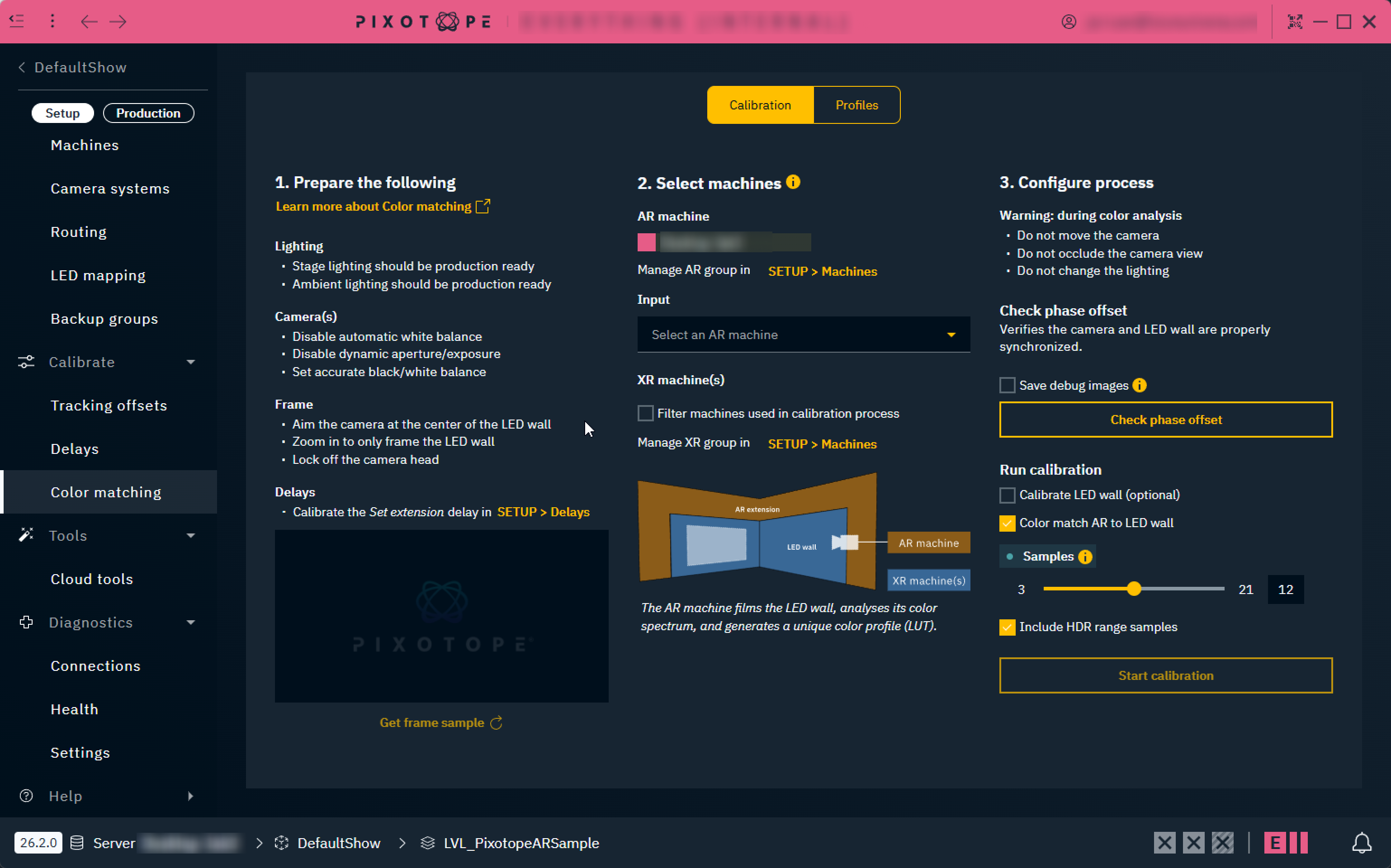
Configure process - Check phase offset
-
Optionally select Save debug images
-
Saves all the frames seen by the AR machine during phase offset detection. This allows to manually inspect if the phase offset is wrong
-
Images are saved on the AR machine into
[Pixotope installation\Services\VideoIO]
-
-
Click "Check phase offset"
-
Black and white colors are projected to check if the camera and the LED wall are properly synced
-
In case a phase offset is detected
-
Adjust the Phase offset on your LED processor and re-check
-
Configure process - Run calibration
-
Specify which calibration steps you would like to run (see below)
-
Set the sample number of the profile
-
Larger values improve the result, but will increase the time for analysis. Values between 7 and 15 usually give good results.
-
-
Optionally enable Include HDR range samples
-
Enable when your camera feed uses an HDR transfer function (e.g. PQ or HLG), so the color matching profile captures the full HDR brightness range
-
This makes the calibration generate test patches with linear values above 1.0. Without this, the calibration never measures how the wall + camera system responds to brightness above SDR levels - sampling continues upwards until the values start clipping, which reveals the maximum brightness the wall and camera can reproduce together
-
-
Start the calibration
The delay between AR and XR needs to be calibrated first.
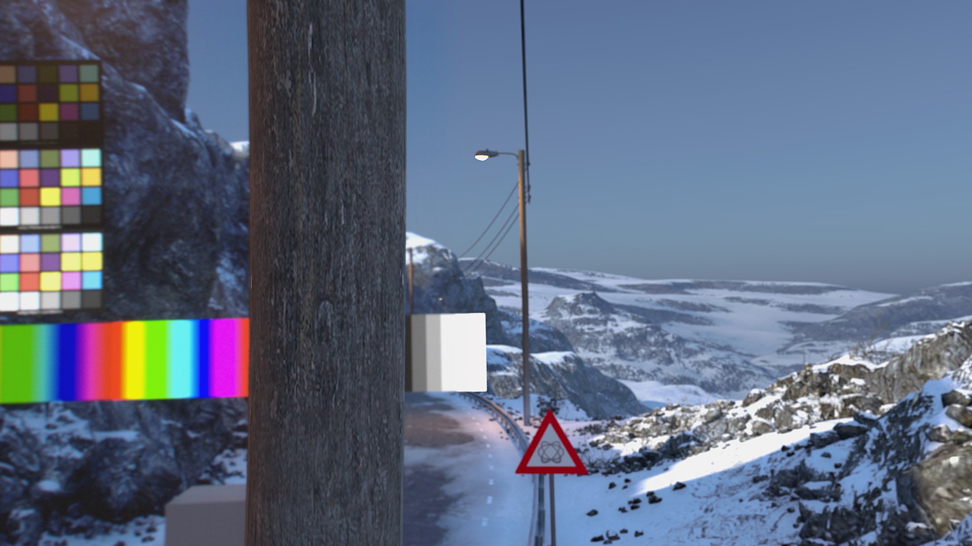
Calibration steps
|
Calibrate LED wall |
optional |
See example images above |
|---|---|---|
|
Color match AR to LED wall |
main step |
See example images above |
During color analysis
-
Do not move the camera
-
Do not occlude the camera view
-
Do not change the lighting
Possible warnings during color analysis
|
Message |
Suggestion |
|---|---|
|
Could not determine the display's latency |
Ensure that the camera is aimed at the display properly and that a valid video signal is present. |
|
Detected latency is X frames |
This happens when latency is more than 30 frames. Consider checking the delay values in Director and that the camera is aimed at the display properly. |
|
CAUTION camera exposure too low |
Increase camera exposure and restart calibration. |
|
CAUTION color gamut clamp |
Check the color format to match the LED’s wall gamut capacity and restart calibration. |
|
CAUTION sync issue during calibration |
May happen on temporary higher latency (e.g. high GPU load in Editor). Check your setup or enable +15 frame delay option and restart calibration |
After color analysis
Any XR machine which was not part of the XR group at the time of analysis, needs to sync and select the profiles manually inside the Profiles page.
Color grading
Using the color grading panel in combination with color matching will deliver varied results. Here are our recommended use cases.
|
|
3D Graphics |
Video |
Final output |
|---|---|---|---|
|
XR machines |
OK, if color grading is the same across machines. |
Not applicable |
Not recommended |
|
AR machines |
Not recommended |
OK |
Making changes to, for example, the video white point should be done through the Color grading panel and not on the camera itself. Adjusting camera parameters (white balance, gain, gamma, exposure) after calibration invalidates the color match - the calibration captured the wall and the camera as one system, so changing the camera changes the system.
Vignetting
Using the Effects panel might be needed to accommodate possible vignetting effect depending on the lens characteristics. Vignette intensity should be increased in oder to extend the darkness effect on edges when appropriate.
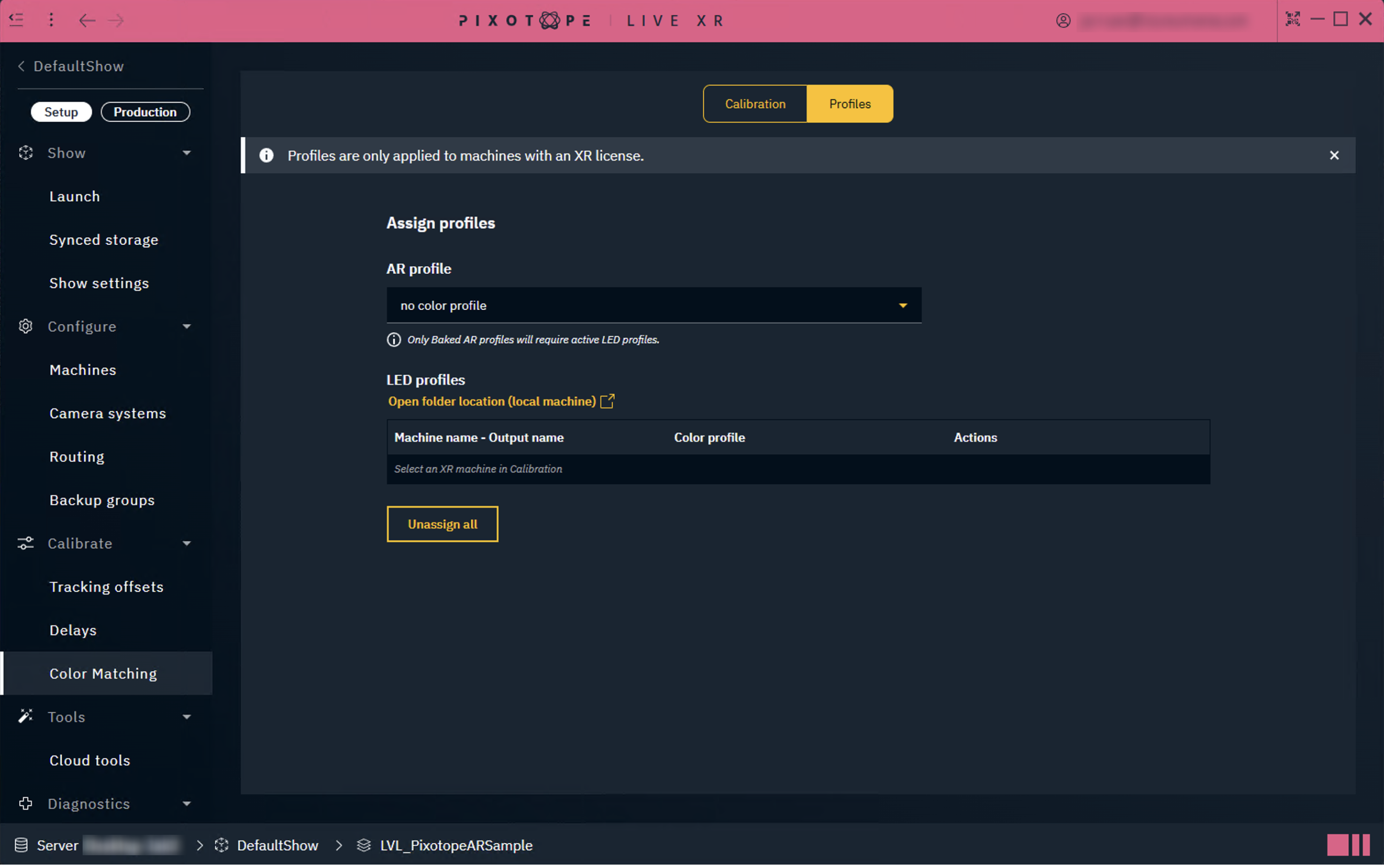
Profiles
This advanced tab allows to
-
manually assign the generated
-
AR profiles
-
LED profiles (AKA XR profiles)
-
optionally limit the profile to a specific mappings
-
-
-
show a Chromaticity diagram for any selected profile
-
unassign all AR & LED profiles selected
Profiles are only applied to machines with an XR license
Chromaticity diagrams
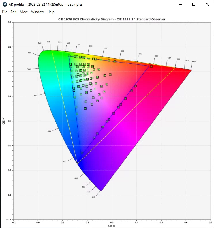
The purpose of this diagram is to visualize color accuracy. In addition, it can help detect if something went wrong during a long calibration process (eg. LED wall occluded by something onset).
How to read this chart:
-
Yellow triangle is the area corresponding to Rec.2020 color gamut
-
Blue triangle is the area corresponding to Rec.709 color gamut
-
Blue square is the theoretical position of the color patch in the Chromaticity diagram
-
Green dot is the position of the color patch in the Chromacity diagram after it is displayed on the LED screen, and was captured by the camera routed to the AR machine
Ideally the green dots will be in the center of the blue squares, but this is not always the case due to imperfect color accuracy of the LED screen. Pure black level is rarely encountered, and LED walls have gamut limitations that prevent the color patch to be shown on gamut boundaries (the blue triangle).
.png?cb=5ba569609a77656e89a1c8b2c1110cdd)
AR profile validation
The state of the validation text changes depending on the type of AR profile selected, and the corresponding LED profiles assigned in the table below.
A Baked AR profile is created when both calibration steps (Color match AR to LED wall & Calibrate LED wall) are enabled when calibrating.
If you have created an AR profile where only Color match AR to LED wall was enabled → Do not assign any LED profiles below
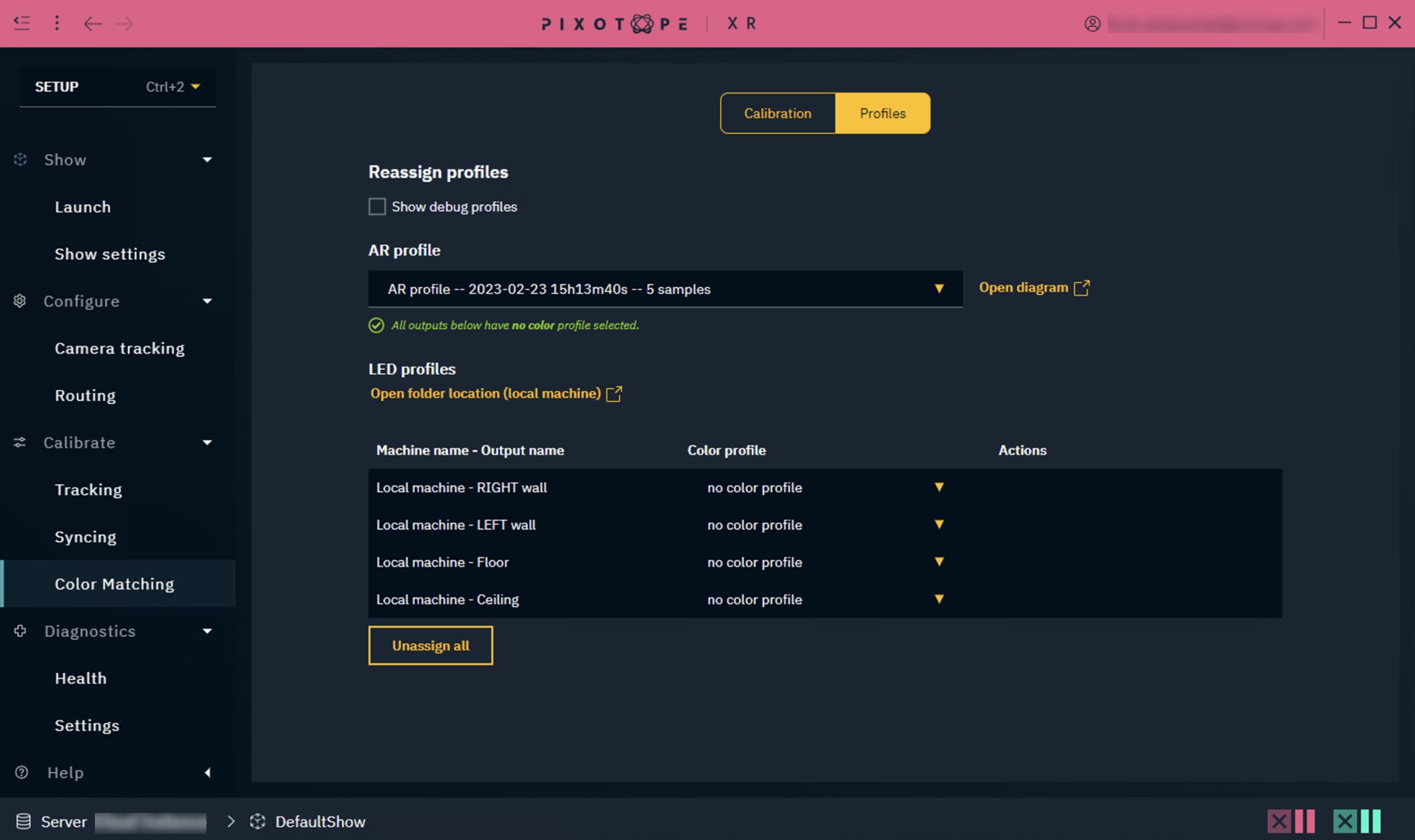
If you have created an AR profile where both Color match AR to LED wall & Calibrate LED wall were enabled → Assign the corresponding LED profiles to all outputs below
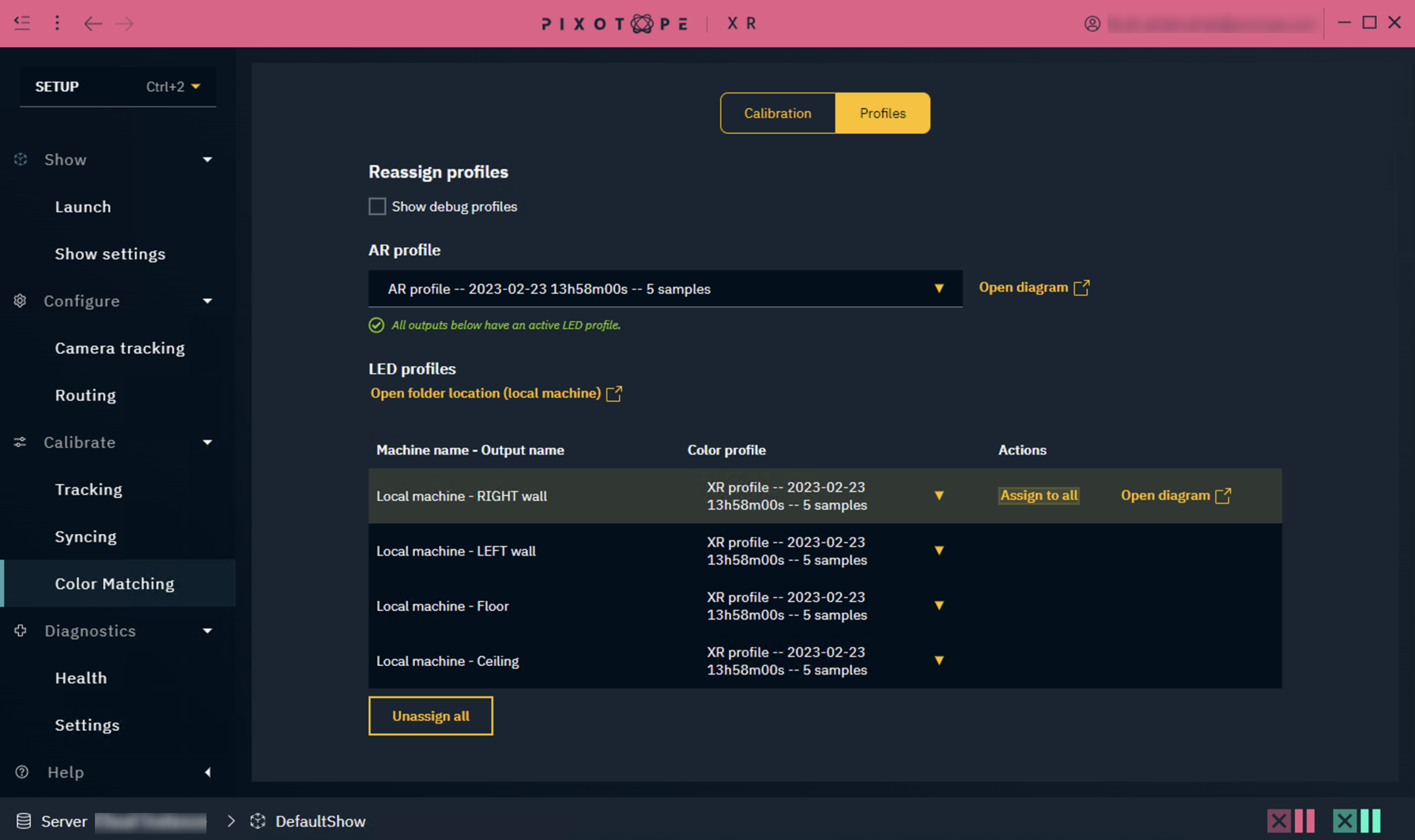
The validation text will keep track of which AR profile you have active, and update based on its specific criteria.
Unassign all will clear both the AR and LED profiles selection.
Profiles storage
The profiles can be found on all connected machines:
...\Pixotope\[Version Number]\Services\VideoIO\ocio-configs\Pixotope XR Calibration
-
AR and LED/XR profiles can be found in the above path as
.cubefiles -
Chromacity diagrams can be found in the above path as
.pngimages