1 Hardware Setup
1.1 Components and Wiring
TalenTrack is available in two setup configurations:
-
One camera per engine: Each camera with a dedicated engine to process its data. This setup provides the lowest tracking data delay of only one frame
-
Three cameras per engine: Three cameras connected to a single engine processing all the data, resulting in a three times higher tracking data delay compared to using only one camera per engine. Multiple engines with each up to three cameras can be combined in order to use the desired amount of cameras
The basic components remain the same for both setups but the network setup will be different, as explained in the dedicated sections below.
1.1.1 Workstation
The workstation requirements can be found in the System Requirements page.
1.1.2 Cameras
The tracking cameras are provided by Pixotope. They are using the following connections:
-
GigE Vision protocol ethernet video connection
-
Power over Ethernet (PoE) power supply
1.1.3 Controls
The workstations are interconnected via LAN. One workstation is defined as server, the others are clients. The server will control the clients through the software and may use the remote control software NoMachine or VNC viewer access (chapter 4 Remote Connection manual). Thus, the server workstation should have display, mouse and keyboard for convenience.
1.1.4 Video and Reference
The server workstation permanently receives an undelayed video input from one of the studio cameras. It is used for pre-visualization and as a reference/genlock.
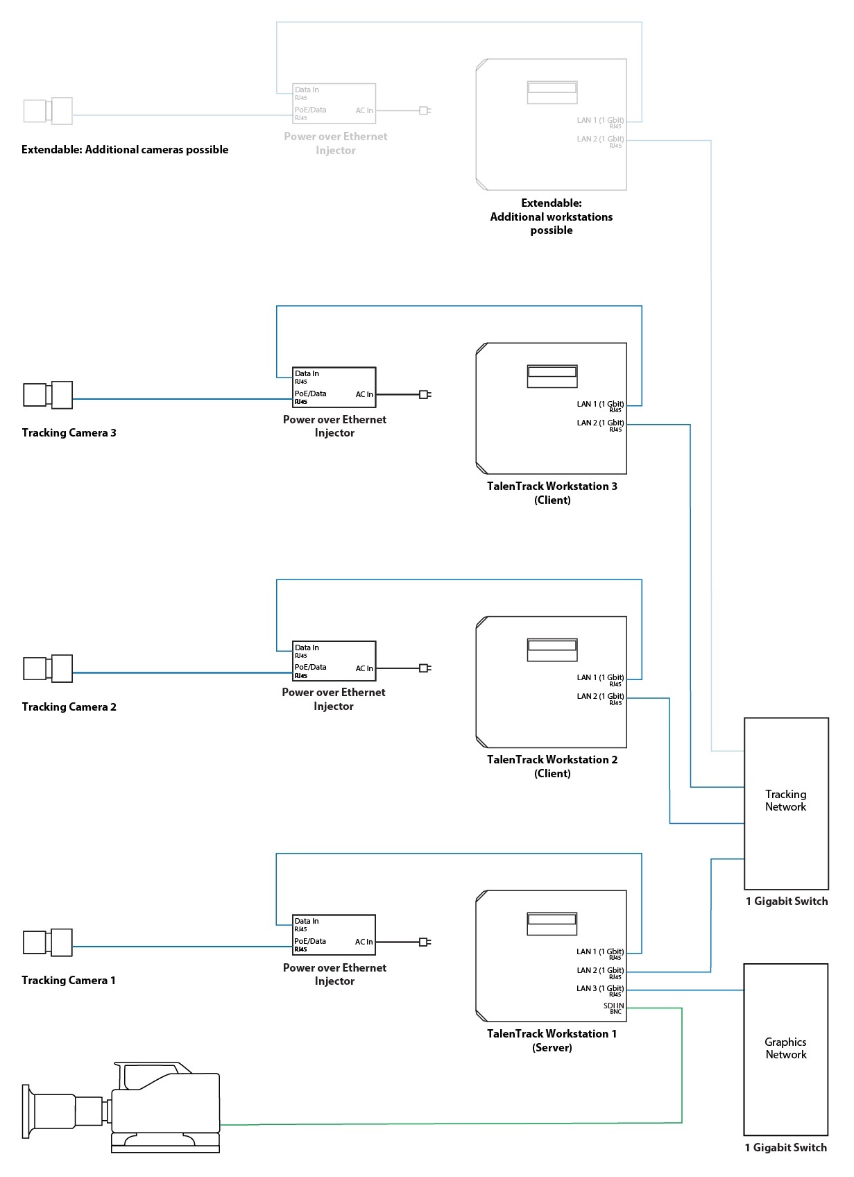
1.2 One Camera per Engine
This employs one workstation per tracking camera, reducing the delay caused by image acquisition and processing to one frame.
The network setup of the system comprises two ethernet connections for Client engines and three for the Server engine.
-
Connection to the Tracking Cameras: A gigabit ethernet direct connection between workstation and respective tracking camera, powered by a PoE injector
-
Connection between the Engines: A dedicated tracking network to connect server and clients. This should be a simple switch with no other traffic on it
-
Connection to the Graphics Network: This connection is exclusive to the server workstation and is used to:
-
Send the talent tracking data to the graphics engine, as well as
-
Receive the camera tracking data in case a Pixotope Tracking camera tracking system is used. This enables visualization tools in the TalenTrack software
-
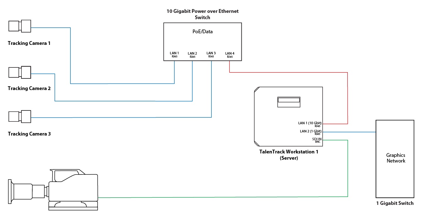
1.3 Three Cameras per Engine
This setup uses only one workstation for every three tracking cameras. This triples the delay compared to using one camera per engine setup. In case 3 talent tracking cameras are installed only one workstation is needed.
The network setup of the system comprises two ethernet connections for client engines and three for the server engine. Each workstation needs a PoE switch to connect to its 3 cameras and a network port to receive the video streams.
Due to the necessity of transmitting three video streams over one cable, this setup requires the PoE switch and the network port receiving the multiple video streams to be capable of 10 Gbit. The following colors are used in the diagrams below for the connections:
-
Red: 10 Gbit (RJ45)
-
Blue: 1 Gbit (RJ45)
-
Green: SDI (BNC)
-
Connection to the Tracking Cameras: A 10 Gbit ethernet connection on the workstation, to connect to a 10 Gbit PoE switch which is connecting and powering all cameras
-
Connection between the Engines: If multiple workstations are used, they will have a dedicated tracking network to exchange data. This should be a simple switch with no other traffic on it
-
Connection to the Graphics Network: This connection is exclusive to the server workstation and is used to:
-
Send the talent tracking data to the graphics engine, as well as
-
Receive the camera tracking data in case a Pixotope Tracking camera tracking system is used. This enables visualization tools in the TalenTrack software
-
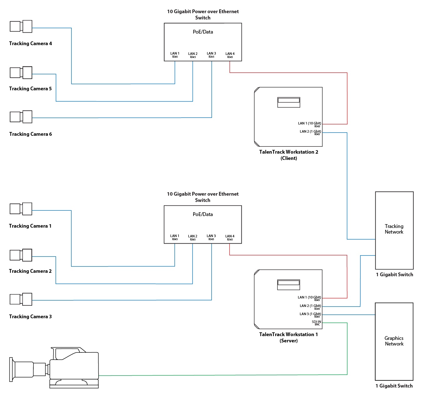
Three Cameras per Engine - 6 Cameras
Two workstations with each 3 TalenTrack cameras can be connected. The connection is established with a 1 Gbit switch between those two workstations. Each workstation needs a 10 Gbit PoE switch to connect to its 3 cameras and therefore a network card with a 10 Gbit network port to receive multiple video streams.
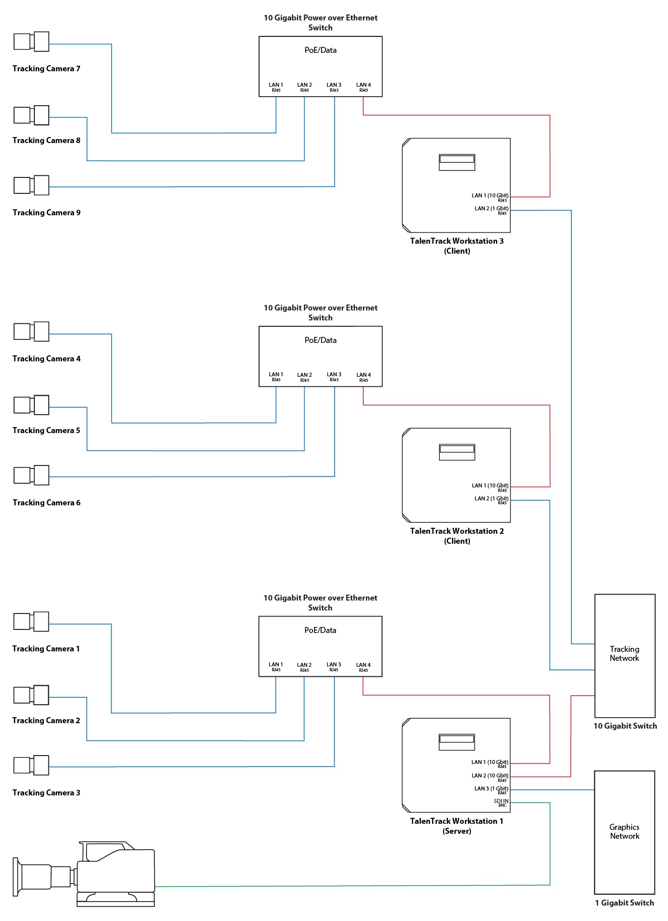
Three Cameras per Engine - 9 Cameras
Three workstations with each 3 TalenTrack cameras can be connected. In contrary to the previous setup, the nine-cam setup needs a 10 Gbit capable switch between those three workstations. Therefore the server workstation needs a second 10 Gbit port to connect to this 10 Gbit tracking network.
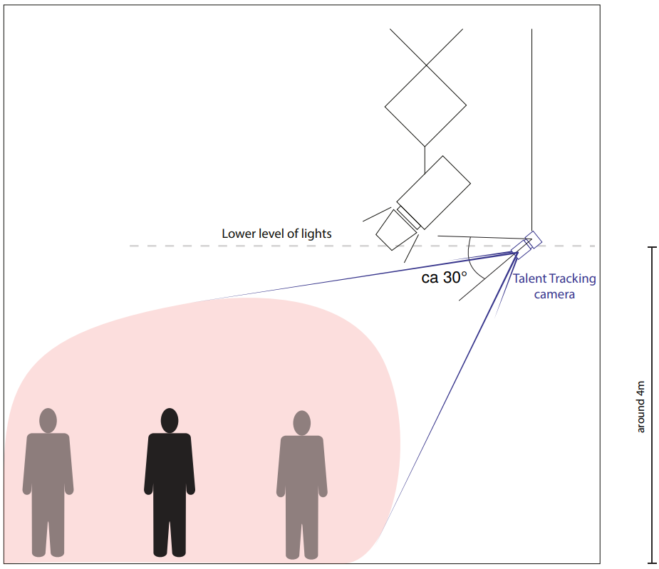
1.4 Camera Installation
A minimum of three cameras with different perspectives is required to create sufficient 3D data to locate a persons entire joints in 3D space. The amount of cameras needed is determined by the area that needs to be covered. Using more than 3 cameras can increase the base tracking area of 5x3 meters.
Their positioning should adhere to the general rules below, if not specified otherwise for the individual use case. The cameras can be installed, connected and then roughly pointed towards the tracking area before the software setup, meaning without video input. Otherwise the software setup can be done before the camera installation with the cameras only connected but not mounted.
The actual lens settings and exact orientation will be adjusted in 3 Camera Settings with the videos running.
-
All cameras must have an overlapping field of view with neighboring cameras. The tracking area is all the area that is covered by 3 cameras
-
A small distance between the cameras should be avoided. Significant distances will turn the tracking data more precise. Keep in mind that the calibration board that will be used during the calibration needs to be seen by neighboring cameras
-
Each camera should have a distance towards the target area center of roughly 6 meters. However, the distance can be closer or further than that because the field of view can be adjusted by changing the zoom of the lens
-
The cameras should look down on the target area at an angle of approx. 30°. Angles steeper than 45° should be avoided
-
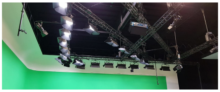
The cameras should be at a height of approx. 4 meters. They should be high enough so that no person or equipment can obstruct the cameras view and low enough so that no lighting equipment in the rig obstructs the view
-
The cameras must be installed upright. It is not possible to flip the image in the software.
2 Software Setup
2.1 Operating System and Software Installation
-
The Linux operating system needs to be installed on all TalenTrack engines. How to do this is described in the OS manual. It will enable the software installation and also remote access for technical support
-
After the reboot make sure that the workstation has internet access on one network port (chapter 3 OS manual). In case no internet access can be granted follow chapter 4.3 of the OS manual to install the software from USB stick
-
In case multiple engines are used they can be accesses over LAN after the OS installation. Remote software comes preinstalled with the OS
-
Open the Software Manager and make sure that the right repositories are enabled (chapter 4.1 OS manual)
-
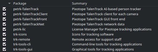
Select the following packages, depending on whether it is a server or client engine
-
Server:
-
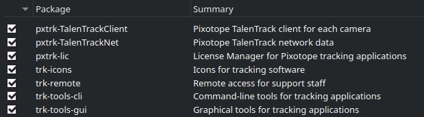
b. Client:
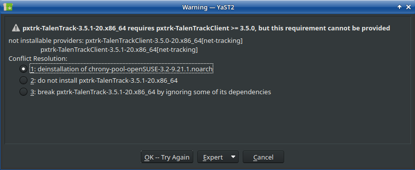
In case a message shows up about the chrony-pool-openSUSE, choose the deinstallation of this package:
-
Reboot the computer after the installation is finished
2.2 Software Configuration
To fully configure the software, the tracking cameras must be connected to the tracking engines.
After the software configuration is done, zoom, focus and aperture of the tracking camera lenses can be adjusted with the help of the video inputs.
2.2.1 Setup Preparations
-
Configure the network settings on all workstations. Which networks are necessary is explained in chapters 1.2 and 1.3 of this manual
-
The connection to the cameras must be the ZeroConf connection on each workstation (chapter 6.2.1 OS manual)
-
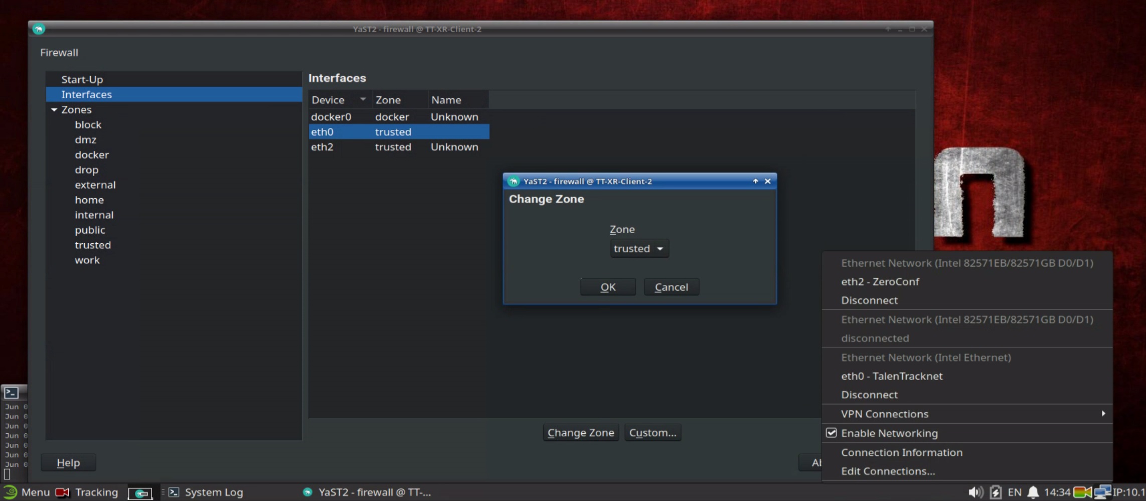
In case multiple workstations are used, configure the tracking network (internal). Keep in mind that in the Network Connection Settings of this connection the Firewall zone needs to be trusted
-
The Server will need to be connected to the graphics network (external)
-
Activate the TalenTrack license on the server according to the Licensing manual
-
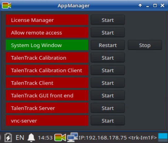
Open the AppManager and right click on its task bar symbol to activate Show All Apps
-
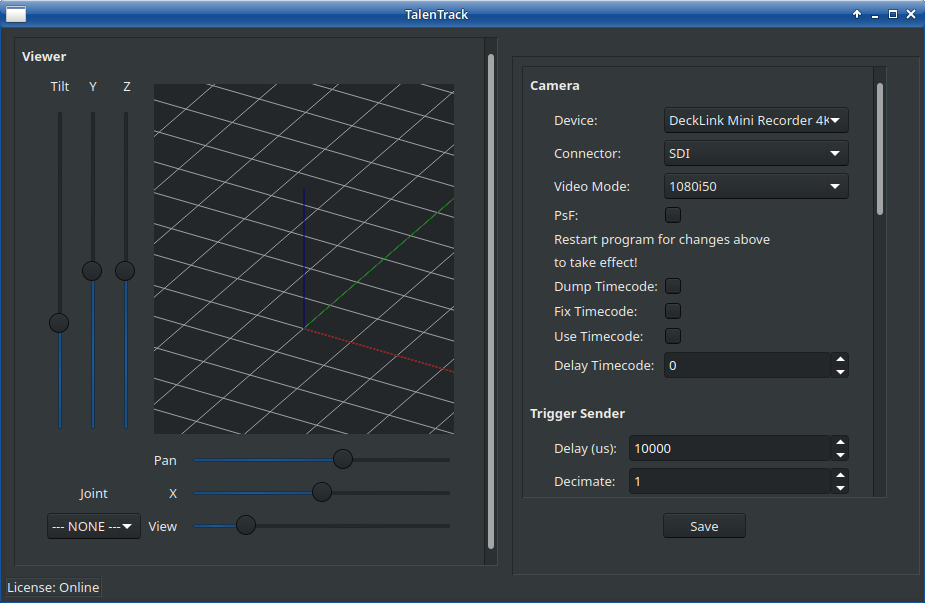
Start the TalenTrack GUI front end
-
Enlarge the TalenTrack window at the bottom to make the Save button visible as shown in Illustration 12. Click Save and Stop the TalenTrack GUI front end in the AppManager
2.2.2 Setup of the TalenTrack Server
-
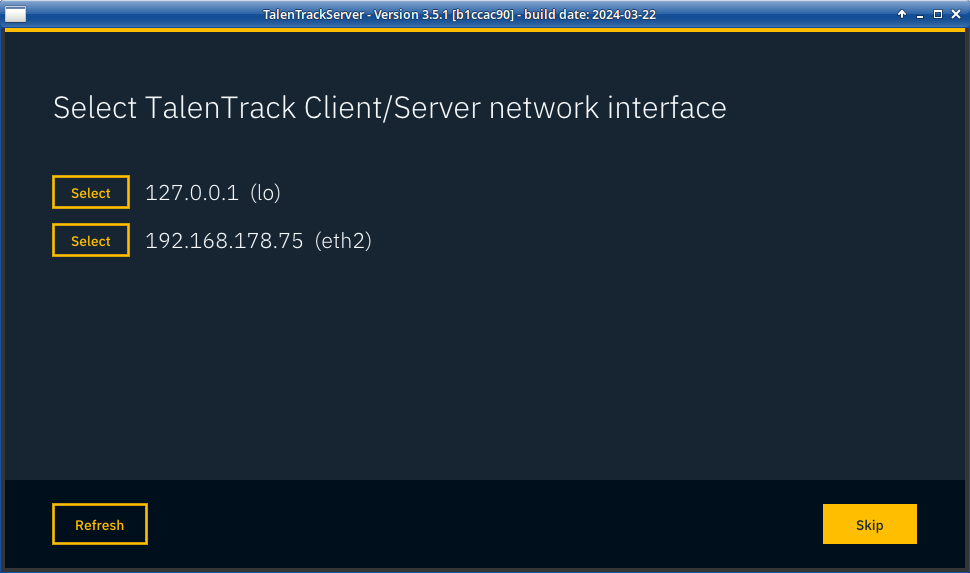
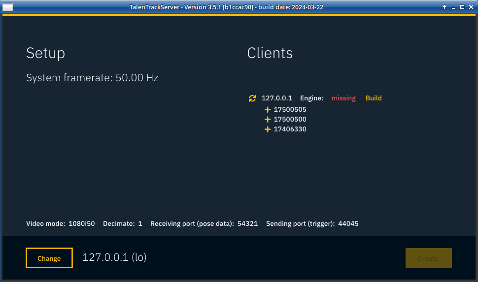
Start the TalenTrack Server from the AppManager. In case no setup has been done before, this will start the setup menu of the TalenTrack Server. After the setup has been done, this setup menu can be accessed in the Server window under Preferences
-
Select the network in which the Clients are. This is the tracking network (internal). In case of using only three cameras on one workstation, select 127.0.0.1
-
If the tracking network is set up correctly, the client workstations should now be listed on the right side. Click Start for all of them
-
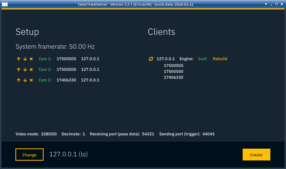
Build the engine on all of the workstations if they are labelled missing. This can take a few minutes
-
Click on the plus sign of the tracking cameras to add them to the setup. The naming/order can be changed by clicking the arrow buttons. This can be changed later in the Server setup menu
-
Click Create to save the setup
-
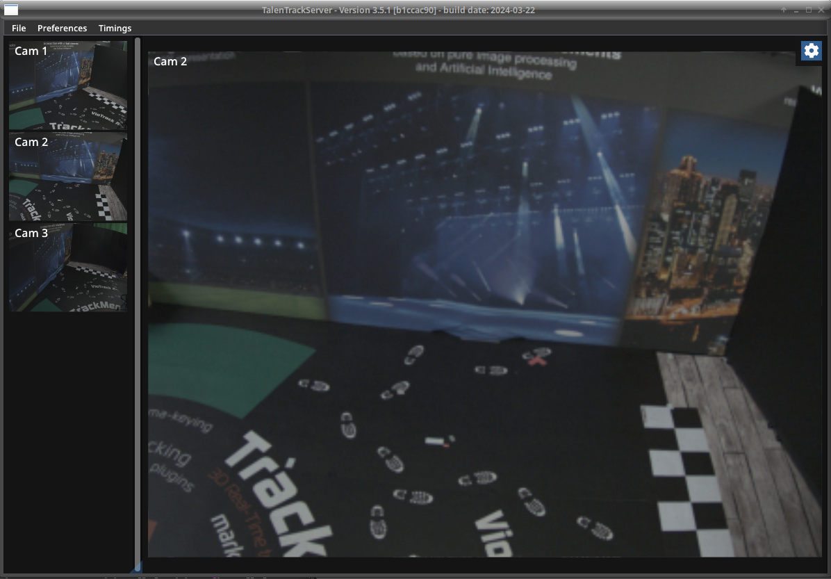
The Server now displays the videos of the tracking cameras
2.3 Firewall Settings
When multiple tracking engines are used, the firewall interface zone of the network connections needs to be set to trusted. To open the firewall menu, type in “firewall” in the search field of the Linux Menu.
3 Camera Settings
3.1 Zoom, Focus and Aperture Adjustment
Before the TalenTrack calibration, the camera settings must be adjusted to see the tracking area in good focus and brightness. Furthermore the zoom should be adjusted so the cameras see mostly the tracking area and not too much of other areas.
At this point the cameras should be mounted according to chapter 1.4 of this site. While adjusting zoom, focus and aperture, it should also be controlled if position and orientation of the cameras are the optimum.
-
Start the TalenTrack Server
-
All camera views are displayed on the left. Click the view of each camera to bring it to the large video window and perform the following steps for each camera:
-
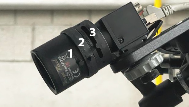
Adjust aperture of the camera: Loosen the iris screw (2) and adjust the brightness. The brightness can be further adjusted in the software, so usually the best is to open the iris fully to see the maximum and then close it a bit to get more depth of field. When content with the iris setting, carefully fasten the screw
-
Adjust zoom (3) and focus (1) settings of the camera: Loosen the two respective screws on the lens. For finding the right settings, always change the zoom first and then adjust the focus. Make sure that the field of view covers the entire tracking area for a tall person standing and moving. Make sure that the person is focused. When content with the field of view and focus settings, carefully fasten the two screws
It is not necessarily desirable to set the lens to the widest angle possible, as precision increases when a person fills more pixels in the video.
-
If needed adjust position and orientation of the camera again with chapter 1.4 of this site to achieve the optimum
3.2 Camera Interface Settings
-
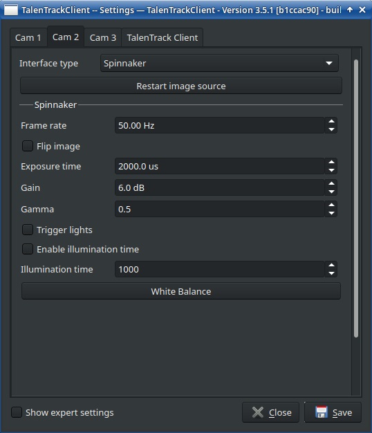
Go to the Client window and click on the cog wheel button in the upper right corner. This opens the settings of the tracking cameras. This may also require to remote log in to a client engine, see Remote Connection manual
-
In the Settings window, switch to the tab of the camera you are working on. Adjust Exposure time (keep below 4000us to avoid motion blur) and Gain (keep below 15dB to avoid image noise) until the video has a good overall brightness, with both dark and bright areas showing as much detail as possible. Keep the Gamma low
-
Click Save