This process requires an XR license for Pixotope Graphics and the Vision or GhosTrack edition of Pixotope Tracking
When doing XR, it is essential to perfectly align the physical LED wall with its virtual representation (XR walls). This is the baseline for projecting graphics onto them and achieving a believable parallax and set extension illusion.
Historically this has been done manually measuring the size and location of the LED wall. Having a LIDAR scan of the geometry helped. This process is obviously quite time consuming and hard, but can still be seen as a fallback solution.
Learn more about how to Create a Manual Twin
Manage Digital Twins
To create more than one Digital Twin version which you can switch between and manage, go to Director > Configure > LED mapping.
Learn more about how to Configure LED mapping
Automatic alignment process
Together with Pixotope Tracking we provide a more automated way of alignment, where image processing is used to scan the actual position and orientation of each individual LED panel.
This is a 4-step process
-
Pixotope Tracking generates a marker pattern which is sent to Pixotope Graphics
-
Pixotope Graphics creates mappings and displays the maker pattern on the LED panels
-
Pixotope Tracking generates Pixotope Tracking Twin data based on the position and orientation of each LED panel and sends it to Pixotope Graphics
-
Pixotope Graphics updates the Digital Twin XR Actor based on the Pixotope Tracking Twin data
1. Generate marker pattern using Pixotope Tracking
Create a marker pattern that covers all LED bodies of the XR stage. You can create multiple patterns by dividing parts of the XR stage into bodies. Each wall, floor or ceiling segment can be a new body. An LED body is one continuous LED surface. A curved LED wall with an extra LED floor would be 2 separate bodies.
Prerequisite: The Pixotope Vision sensor camera needs to be calibrated. Meaning that a lens file has to be made.
1.1 Marker Layout
-
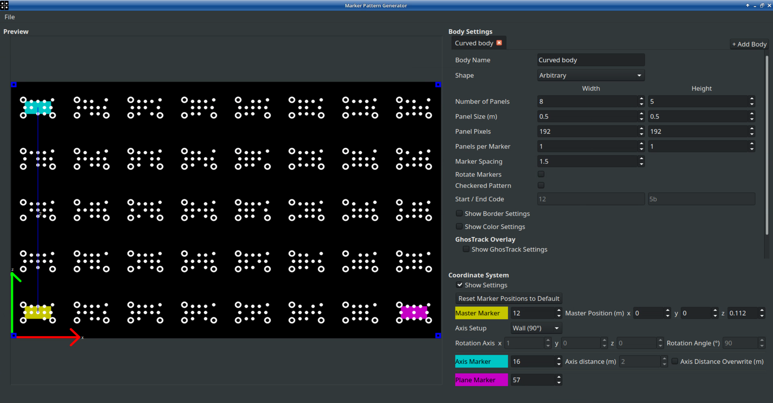
Open the Marker Pattern Generator:
-
Click + Add Body on the upper right side to add as many bodies as you need.
-
The bodies do not have to correspond to the video output routing. In general, all LED panels that form a single shape, should be a single body.
-
Each LED part disconnected from it, such as ceilings, floors or totems, should become individual bodies.
-
Each LED portion that uses different panel parameters, like Panel Pixels or Size, than the others will also require their own body setup. Name them to be able to identify them.
-
-
For a Digital Twin the Shape should always be Arbitrary.
-
Enter the specifications of the LED panels which you are using. That is: Number of Panels, the Panel Size in meters and the Number of Pixels that one panel consists of. This information refers to that specific body and can differ between multiple bodies.
-
With Panels per Marker you can extend one marker over multiple panels. This may be applied when markers on a single panel are very small in relation to the LED wall size, and they might become hard to recognize from distances in which the whole wall can be seen.
If multiple panels display a single marker, these panels must be completely planar and can not have an angle between them! If the wall is curved, most of the time the panels in one column, above each other, share the same orientation and are available for 2 panels per marker. -
Marker Spacing determines the space between the markers. As a rule of thumb we recommend the empty space between the markers to be half the size of a marker. If the space between markers is too small there can be interference in the individual marker detection.
-
Rotate Markers rotates the markers by 90 degrees. Since the markers are wider than high, this enables you to expand one marker over two panels vertically. A curved LED wall is a use case for this, as explained in point 5. The markers can be larger that way, requiring less Marker Spacing.
-
Checkered Pattern removes every other marker. This enables you to increase the size of the markers without any interference between them. In general, this setting should be avoided because it relies on extrapolating existing data for missing markers.
-
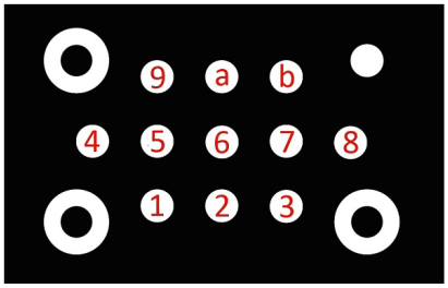
Start / End Code refers to the code of the first and the last marker of this body. Every Marker as a unique code which is determined by its missing dots in an ascending order, as shown below. This is filled in automatically and will only need to be touched if multiple pattern configurations are being used in the same space, and they need to be able to be told apart.
-
Border Settings can be used to remove a line or column of markers at the edge of the body, in case they can not be visible during calibration. These panels will then be extrapolated from other panels data.
-
Color Settings can be used to change some colors for convenience.
-
A GhosTrack pattern can be created when enabling the GhosTrack Settings. This will create a second pattern version that replaces most of the markers with a custom image. The image should provide feature points to the tracking that are more distinct corners than the repetitive circles, but have markers remain in place to enable Auto-Init.
-
The Export Image button exports the pattern as a .png file.
1.2 Coordinate System
Set up the coordinate system of the pattern. Note that this is a setting that happens in a single body only - all other bodies use that body and it’s coordinate system for reference.
The coordinate system used for the XR scene will be defined in the Marker Calibration process. However, it can be pre-defined in the pattern by selecting markers. These will also be used for calculations, so the selection is mandatory.
The preferred setup for a wall is to have the lower left corner as the origin and have the X-axis going through the lower right corner of the LED wall. The Z axis then goes upwards along the edge of the LED wall.
-
Choose Master, Axis and Plane marker by right-clicking onto the respective markers. These three markers determine origin, axes and scale of the coordinate system:
-
The Master Marker determines the position of the origin. It is by default in the lower left corner of its panel.
-
The Axis Marker determines the first axis (Z for LED wall setup or Y for LED floor setup).
The Axis Marker also determines the scale by its distance to the Master Marker. A blue line drawn into the pattern preview indicates this. Mind that this scale will not be measured but calculated by the number of panels! That means Master and Axis Markers have to be in one plane and not angled towards each other! (e.g. the panels in a straight column of a curved wall) -
The Plane Marker determines the second axis (X for LED wall and floor setup)
-
For the coordinate markers, choose the markers that are far apart from each other, because a larger distance allows more precise calculations.
-
Select Axis Setup. This will determine whether the coordinate system will result in the body with the Origin Markers to be a floor, ceiling or wall.
-
Choose the Master Marker and Master Position. Master Position offsets the position of the origin from the default position. The default position ( Master position = 0,0,0) is the lower left corner of the Master Marker panel

Master Marker options
If an LED wall is above the ground, it is possible to offset the Master position down to the floor directly underneath it. For example, if the LED wall is 15cm above the floor and the lowest left marker is selected as Master, put 0.15 into the z-field of the Master Position. This will offset the entire X-axis to the floor.
The coordinate settings can also be defined “manually” by clicking onto three points in the reconstruction, as described in the Pixotope Tracking manual. This will overwrite the coordinate setup defined in this chapter.
Please be aware that an LED wall might not be perfectly 90 degrees upright. So defining the coordinate system with three points on the wall or three points on the floor can result in different axis angles.
1.3 Sending Pattern to Pixotope Graphics
-
Save the configuration file locally (usually /home/tracking/pxVision/VioStudio.cfg) using the “File” menu in the top left corner
-
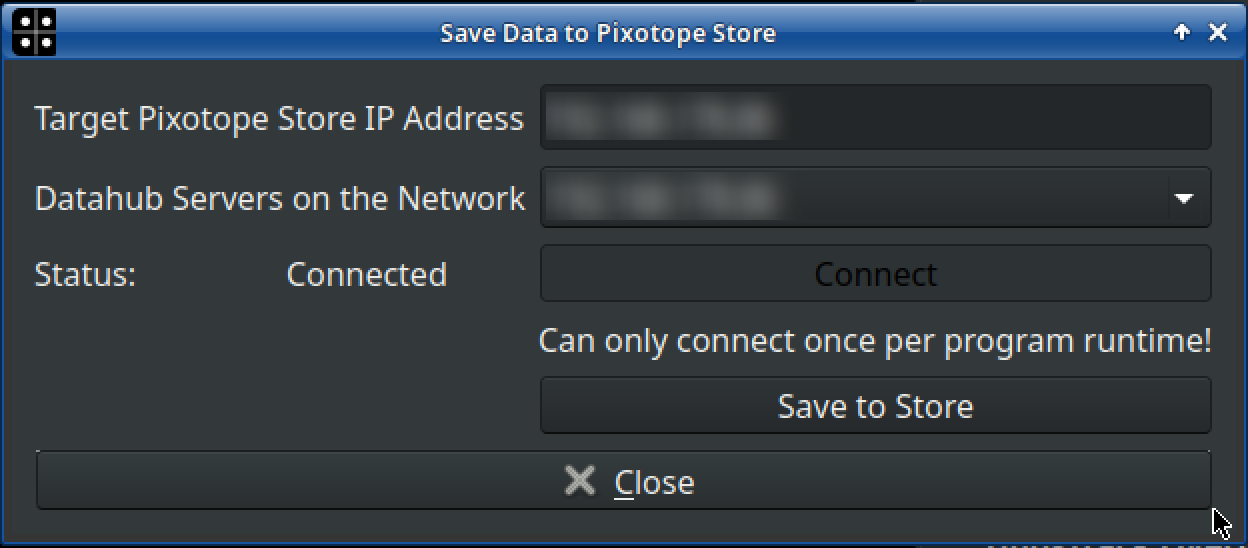
To save the marker pattern configuration as well as the marker pattern .png-file onto the Pixotope Graphics Engine, click Save to Pixotope Store using the “File” menu in the top left corner
Please be aware that
-
the Pixotope Graphics engine you are sending to must be running as a Server
-
Change in START > Machine Settings > Role
-
-
the encryption has to be disabled for the Pixotope network you are on
-
Change in START > Machine Settings > Encryption
-
-
Select the IP address of the Pixotope Engine and Connect. Then Click Save to Store
The same marker pattern can be used for calibrating the offset between the sensor camera and the film camera as well as for determining the optical parameters of your zoom lens. Also the AutoInit function will use the same markers. Please see the Pixotope Tracking documentation for more details.
2. Create mappings using Pixotope Graphics
2.1 Create the initial Pixotope Tracking Twin
-
Open your XR level in the Pixotope Editor
-
Add the Digital Twin XR actor to your scene
-
The actor gets automatically placed as a child underneath the Camera Root
-
The actual Digital Twin data (Bodies, XR walls, mappings, 2D media) is stored in the Show file. When sharing projects containing a Digital Twin, the Show file needs to be included!
-
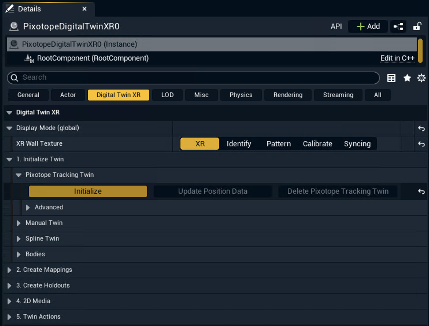
Click the "Initialize" button in Digital Twin XR > 1. Initialize Twin > Pixotope Tracking Twin
-
For every single LED tile of a body, an XR wall actor is being created
-
At this point these XR walls are displayed in a plane and are not yet positioned correctly.
Copied an existing Digital Twin actor?
-
Click the "Regenerate" button under Digital Twin XR Regenerate
This restores the references between digital twin data and the wall actors.
2.2 Create mappings and select output machines
Learn more about how to Create mappings
2.3 Display the tracking pattern
-
Expand Display Mode
-
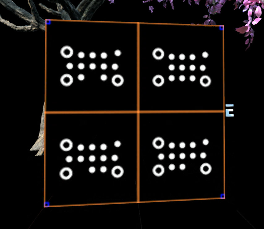
Choose "Pattern" for the XR Wall Texture
-
The colored squares in the corners of the pattern must match the corners of the LED pattern.

3. Generate Pixotope Tracking Twin data using Pixotope Tracking
3.1 Setup Data hub connection
-
Start "Pixotope Vision Marker Calibration" (or "GhostTrack Marker Calibration")
-
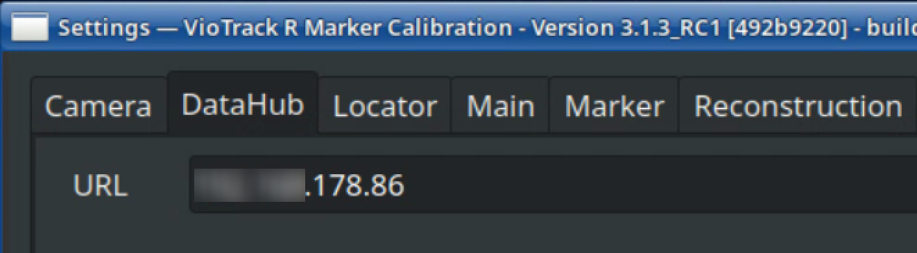
Open the Settings and activate “Show expert settings”
-
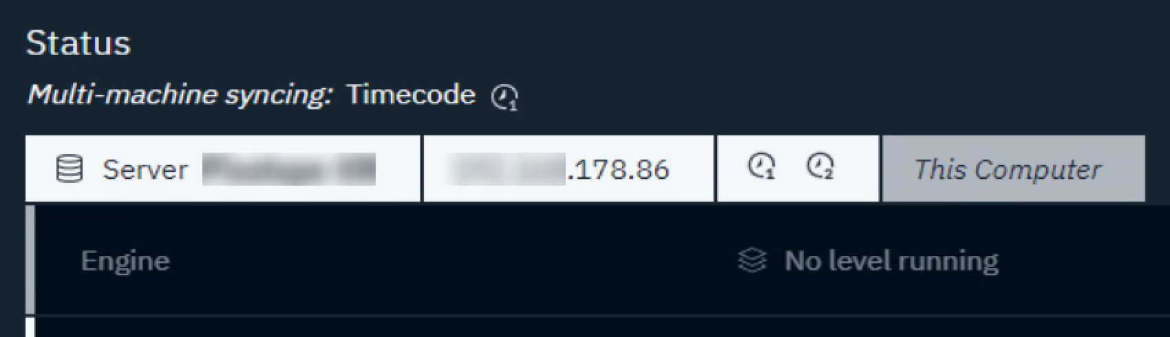
Go to the DataHub tab and enter the Pixotope Data Hub IP address which can be found in Director > Status panel (lower right corner in the Director)
-
Save and restart "Pixotope Vision Marker Calibration" (or "GhostTrack Marker Calibration") to have the program connect to the Pixotope Data hub
3.2 Marker Calibration: Generate the digital twin data and send it to Pixotope Graphics
-
Start "Pixotope Vision Marker Calibration" (or "GhostTrack Marker Calibration")
-
Configure to use the sensor camera and the correct lens file and set the video settings for good visibility
Note: for the Marker Calibration process itself, it may be beneficial to use a high-quality lens of the broadcast/film camera instead of the sensor unit of the tracking system. This camera is also more likely to have a good view of the LED volume which might be more complicated with a mounted sensor unit. Check the expand above for details.
-
Perform a reconstruction of all LED bodies including each marker from different angles and positions. Make sure to have multiple samples of each marker. Check the expand for more details
Marker recording procedure
-
Start with perspectives that have the full wall with all markers in view, if at all possible
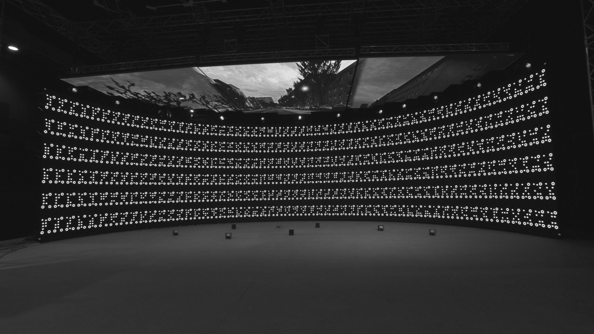
-
Move around to have different perspectives, mind having a good number of markers in view for reference. Do not get too close.
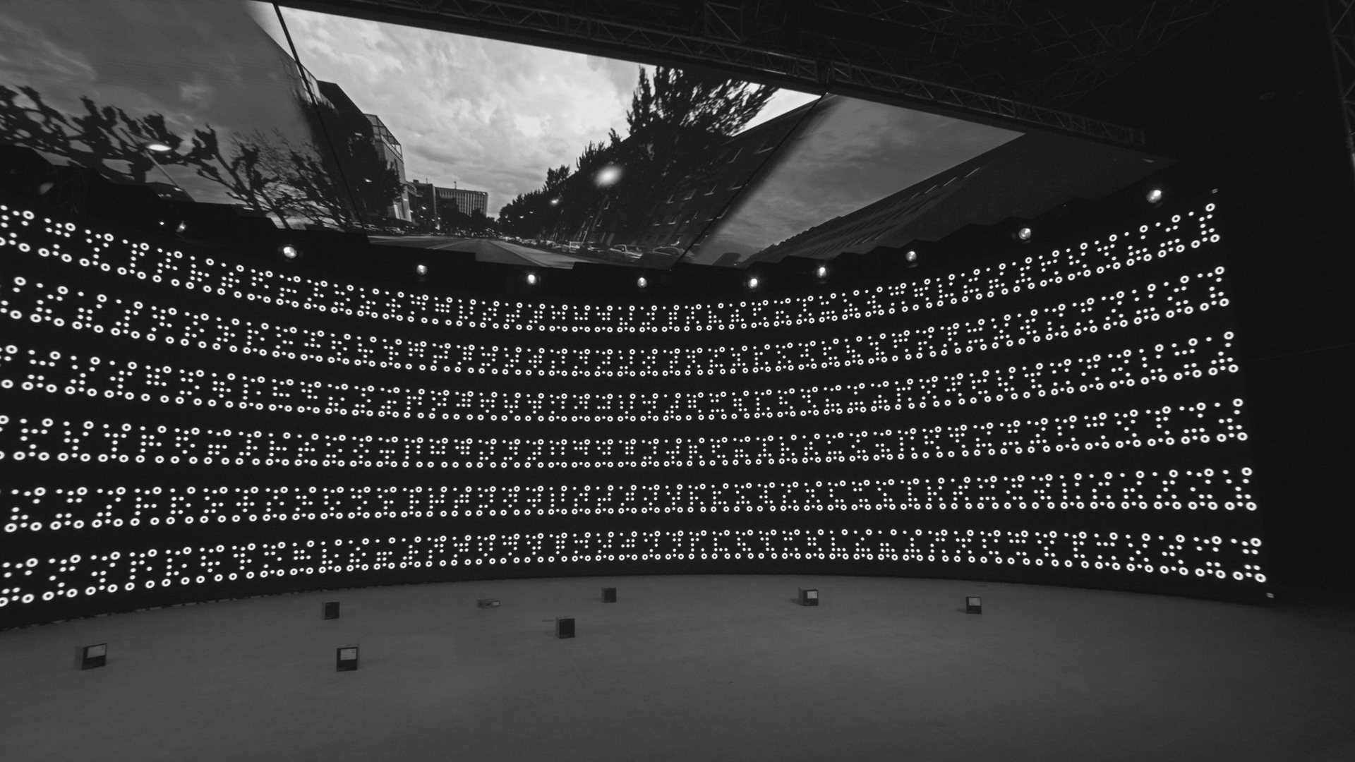
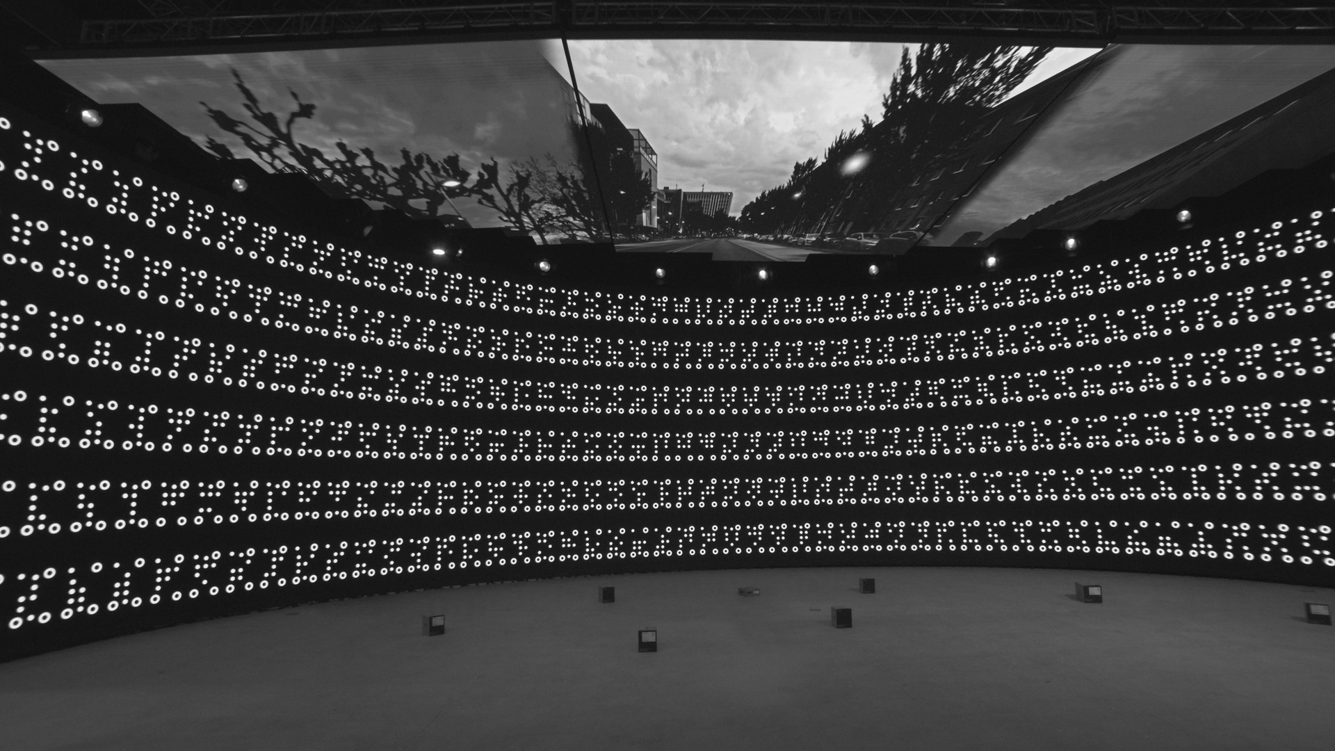
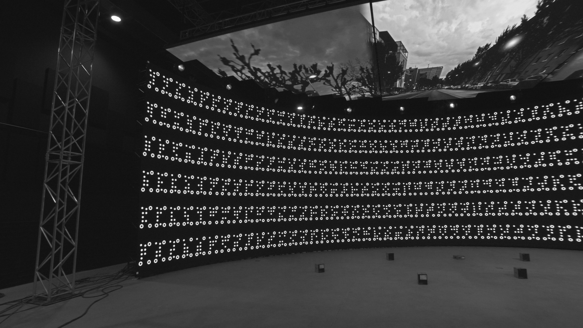
examples of getting different angles but still seeing many markers -
Try having each marker somewhere near the image center for a few samples. The center parts of the image are less affected by distortion than the outer parts, so aim at the corners and the top and bottom of larger walls too.
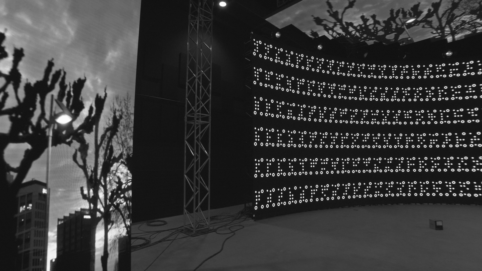
Even though “wasting” half the image by not having markers in it, it’s worth it to have the markers on the edge near the image center 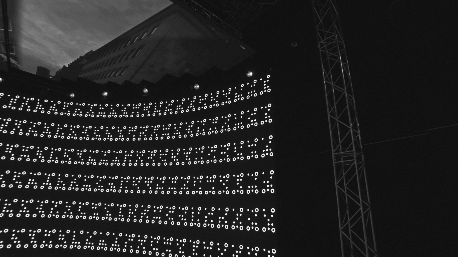
Mind the corners and upper and lower edges of the wall too, capture them near image center as well -
Even with large walls, less than 100 recordings should be enough. More recordings are less likely to give better results than they are likely to introduce images with motion blur or similar negative effects.
-
Open the Marker Calibration menu
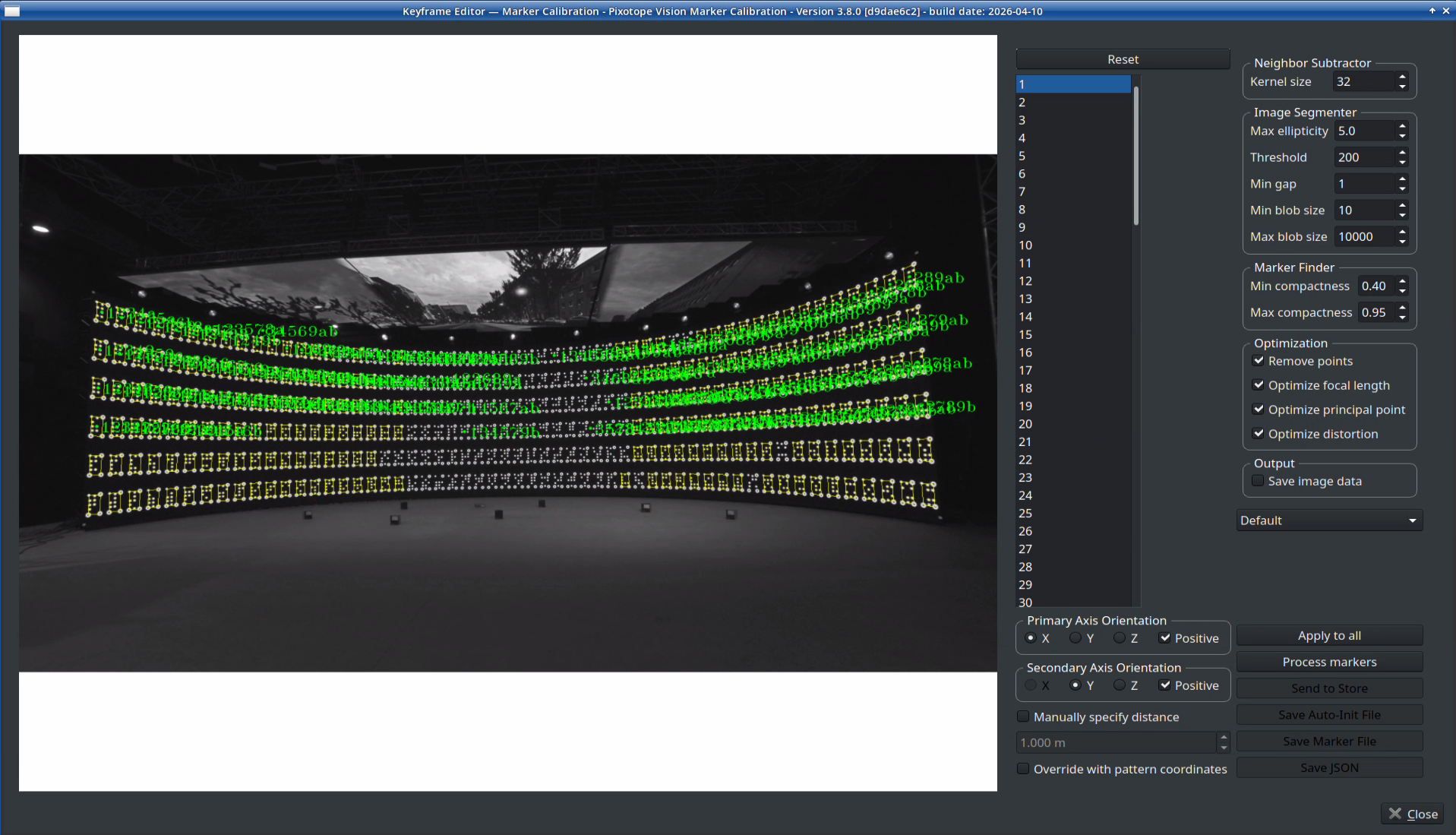
Marker Calibration window -
Make sure that the program sees and identifies as many markers as possible (indicated by the yellow marker detection, the green numbers can be ignored).
-
Find the ideal Threshold value in the Image Segmenter section on the right side. Selecting Binary mode in the dropdown menu and zooming into the image with the mouse wheel can help estimate the value.
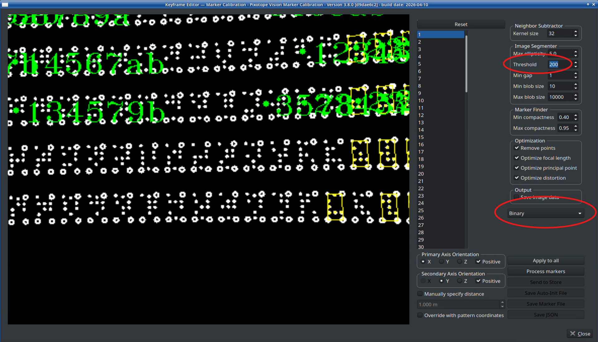
-
Click Apply to all to use the threshold in all keyframes
-
Move on to scan through the keyframes, checking some of them whether the threshold is a good choice. If a different threshold gives better results for specific perspectives, adjust it and click Apply to all again to add additional data.
-
-
Optional: determine the origin, orientation and scale manually:
Manual specification
-
Refine the coordinates by clicking in the Keyframes, as described in Setup Checklist | 4.2 Defining the orientation . this will overwrite the coordinate system setup done in the Marker Pattern Generator
-
It makes sense to put the zero plane on the floor. For being able to click on points on the floor, place marks like tape underneath the corners of the LED wall.
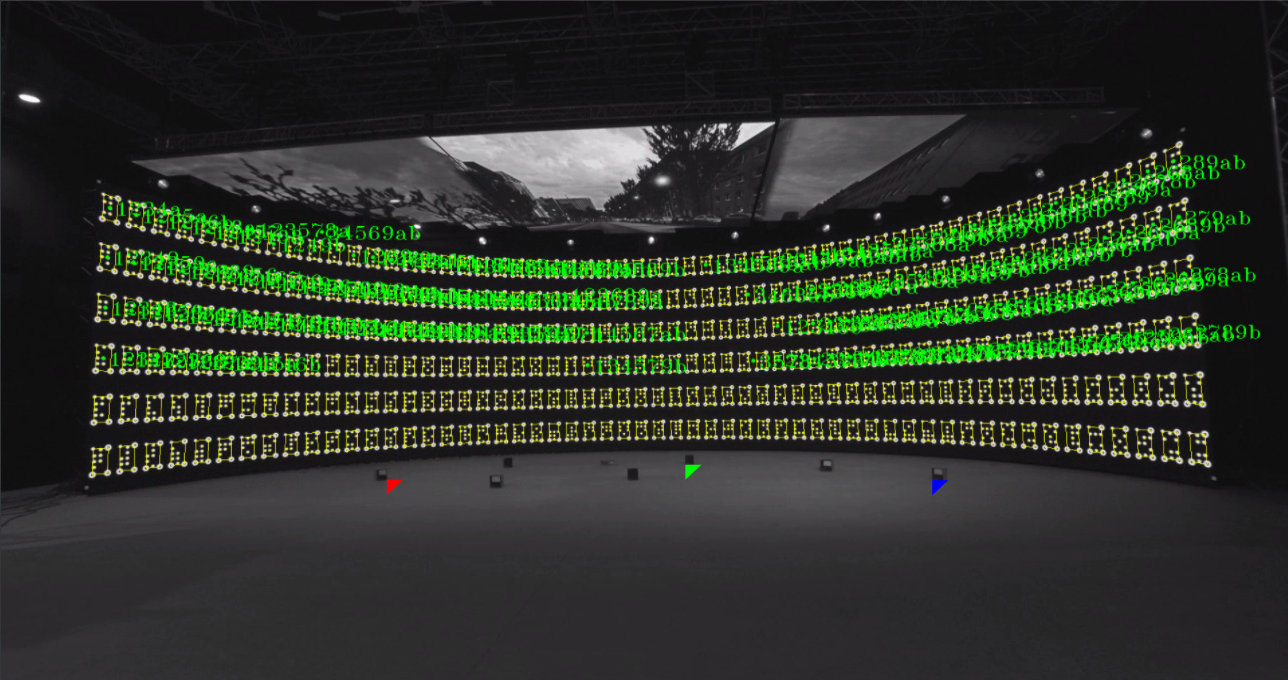
Exemplary selection of markings on the floor for putting the origin -
If you also want to set the scale manually, enable Manually specify distance and type in the measured distance between the red and the blue point
-
The hand-picked points will overwrite the pre-defined, marker-based points from the pattern generator automatically when an arrow is set and until either Reset or the option Overwrite with pattern coordinates is selected.
-
Remember to set the axes correctly. They don’t have to correspond to the wall corners. They will set the origin of the level!
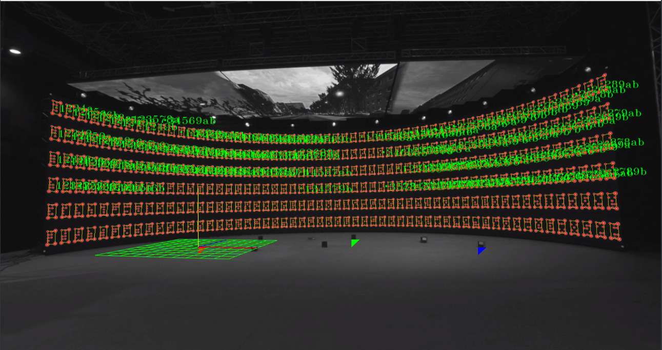
Result after processing the markers
-
Click "Process Markers", wait for the process to finish and check if theoretical position of markers (in red) matches the actual markers and if the coordinate system is correct. a grid will indicate the origin and the three axes as well as the zero plane.
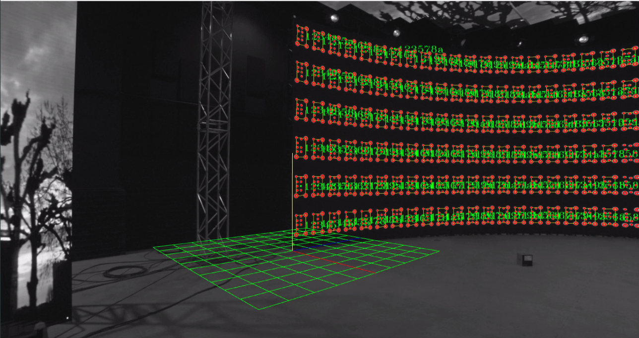
-
Scan through some keyframes and check the result. If content, click Send to Store to send the data to Director.
-
Save the AutoInit file (“AutoInit.cfg”) and the Marker file (“VioMarker.cfg”) in the folder /home/tracking/pxVision.
The Pixotope Tracking Twin data can later be used to fine tune the precision of the tracking. Please see the Pixotope Tracking documentation for more details.
4. Update the Digital Twin
-
Click "Update Position Data" in the Digital Twin XR actor in the graphics engine. This will apply the Pixotope Tracking Twin data to this actor and thus reshape and relocate the XR wall(s).
If the pixel data of the LED wall has changed, existing mappings have to be recreated.
Enable Auto Update Digital Twin to continuously read the Pixotope Tracking Twin data sent from Pixotope Tracking. This is mainly used for testing.
To completely start over:
-
Click "Delete Pixotope Tracking Twin”
This will reset the Digital Twin XR actor and delete all related XR walls.
The digital twin data which was sent to Pixotope Graphics is NOT deleted.
Check your alignment using an AR machine
Learn more about how to Check your alignment
Manage XR holdouts
Enable XR holdouts when using a virtual set extension.
Learn more about how to Manage holdouts