Create mappings to define which LED panels/XR walls render to which video outputs. This step connects your physical LED setup to Pixotope's rendering system.
Key Concepts
-
Mappings work identically for manual setups and digital twins
-
Mapping is a 2D process, independent of physical LED body shapes
-
Without mappings, XR and digital twin patterns won't output
Mapping example
The following example LED bodies
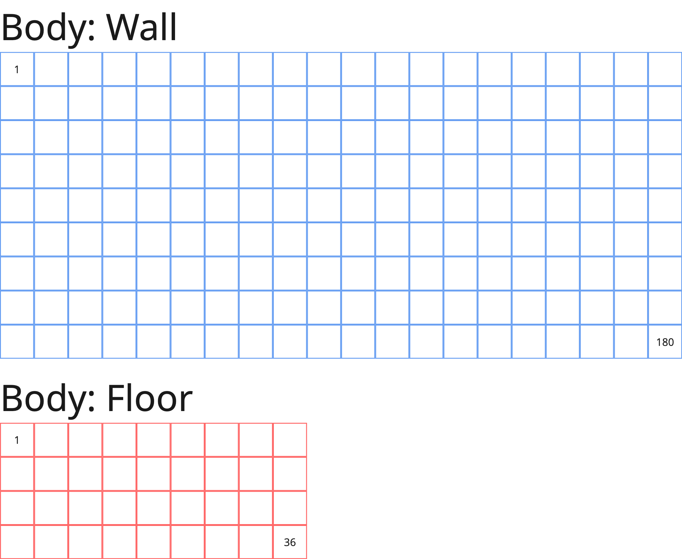
can be output in different ways:
|
Render each LED body by a single machine. Check out LED wall smaller than a single output |

|
|
Split up the large LED body and render it by multiple machines. Check out LED wall larger than single output |
|
|
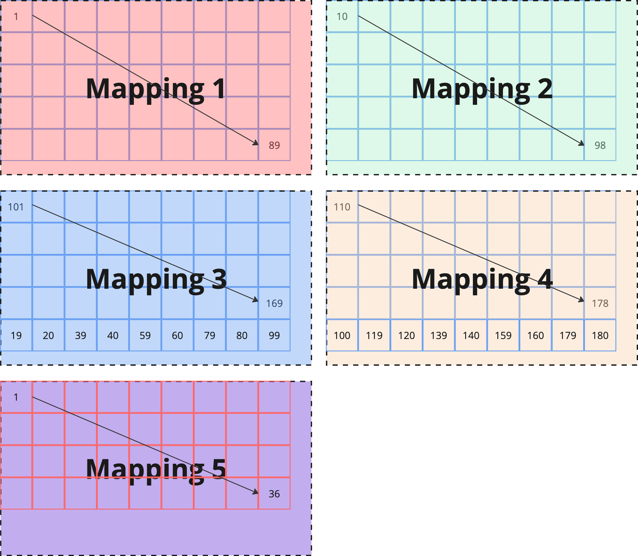
Render all LED bodies by a single machine. |
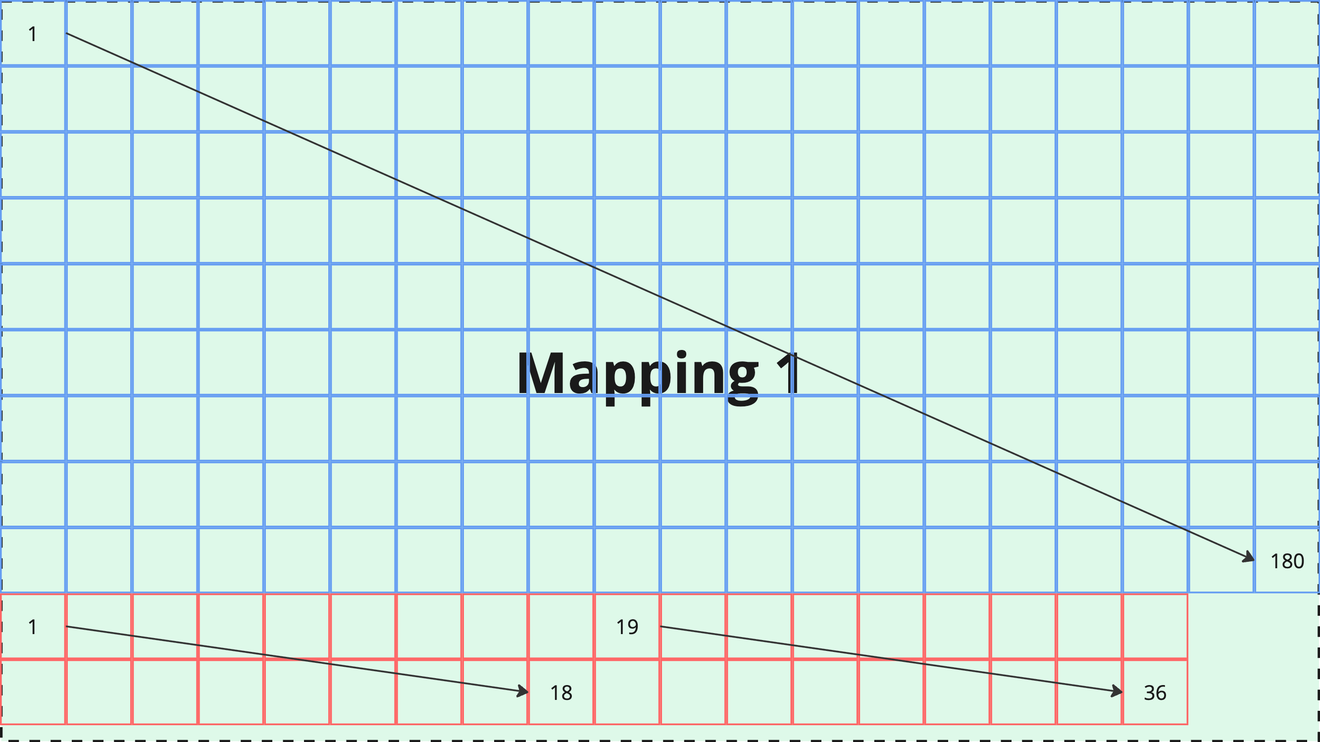
|
Prerequisites
-
Complete the body generation
-
Know your LED body sizes and resolutions
-
Determine your required number of outputs
Create mapping: LED wall smaller than single output
When your LED wall has a lower resolution than a single Pixotope output, you can create a straightforward one-to-one mapping.
Example LED Wall Configuration
Consider an LED wall with 9 × 5 panels. If each panel has a resolution of 384 × 384 pixels, the total wall resolution would be 3456 × 1920 pixels.
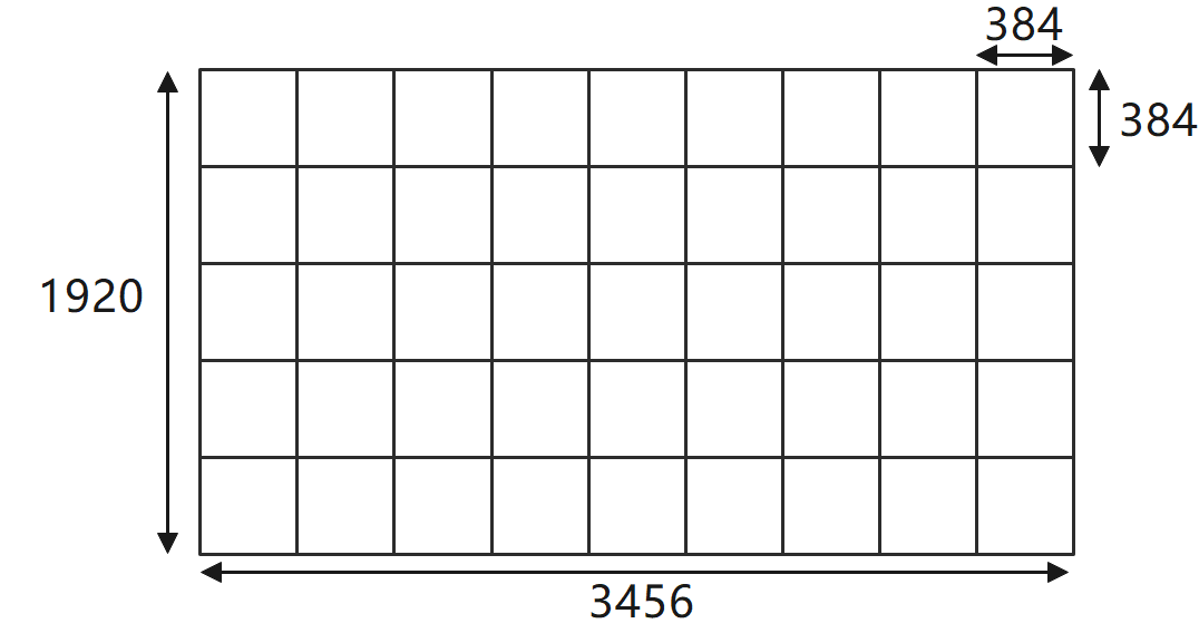
In the Digital Twin actor, LED panels (XR walls) are named starting from the bottom left panel of the LED body.

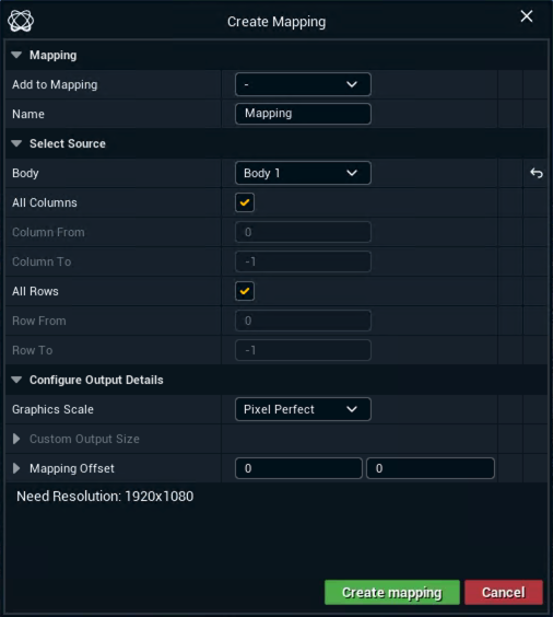
Create single mapping
Since the resolution of this LED wall (3456 × 1920) is smaller than a single Pixotope UHD output (3840 × 2160), you can create a single mapping with these steps:
-
Open the Details panel of the Digital Twin XR Actor
-
Click "Create Single Mapping"

-
Add to Mapping: Leave blank (-)
-
Give the mapping a name
-
Body: Select the LED Body you want to creating a mapping for
-
Keep All Columns and All Rows selected
-
-
Graphics Scale: Choose "Pixel Perfect"
-
this ensures pixel-to-pixel display on the LED
-
Double check the Needed Resolution on the bottom.
-
Click "Create mapping"
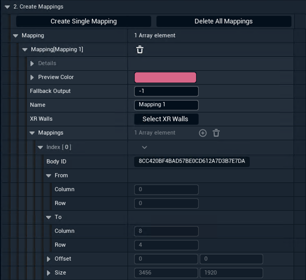
A single mapping is created.
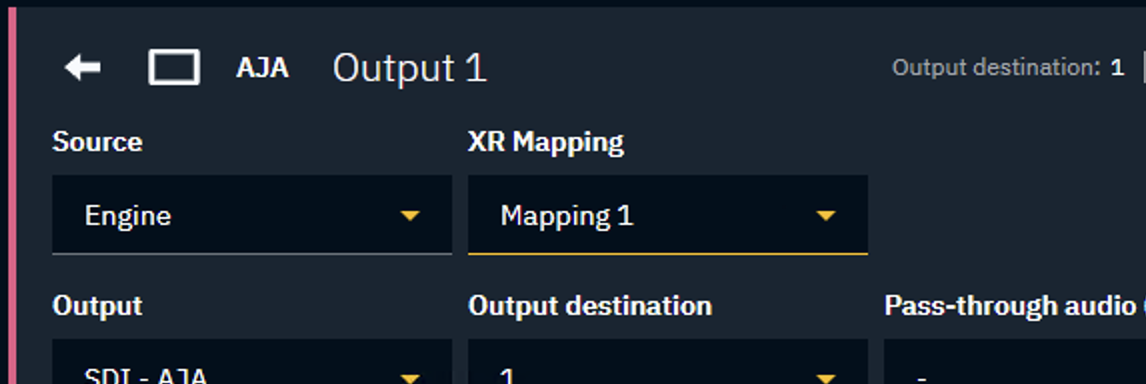
Route output
-
In Director: Go to SETUP > Configure > Routing
-
In the XR Mapping dropdown of that machine, select "Mapping 1"
Make sure that the machine has an XR render group tag.
Learn more about Render, feature and custom groups - AR, VS, AR+VS, XR
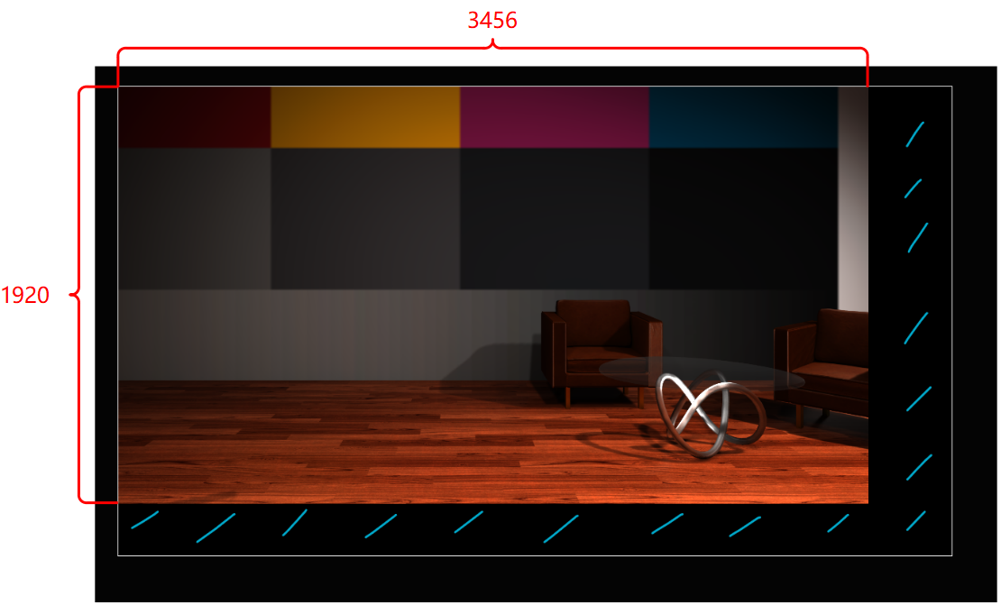
Verify output
After creating the mapping, your XR output will display the texture with the following characteristics:
-
The XR texture will occupy only part of the output (3456 × 1920 pixels)
-
The unused portion of the output will appear black
-
The LED processor needs to extract the relevant pixels and display them on the physical LED wall
|
Display mode: XR |
Display mode: Identify |
|---|---|
|

|
Learn more about how to identify your mappings below
Create mapping: LED wall larger than single output
Example LED Wall Configuration
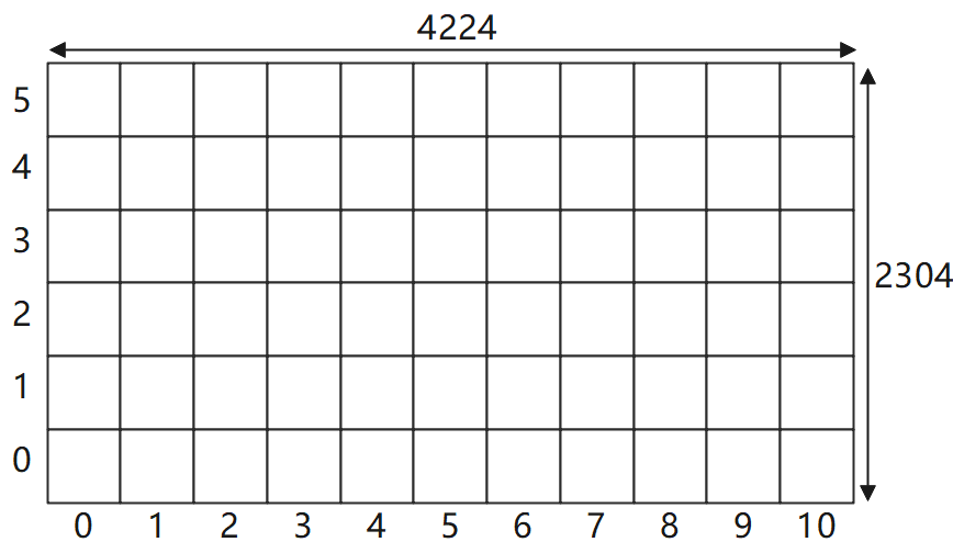
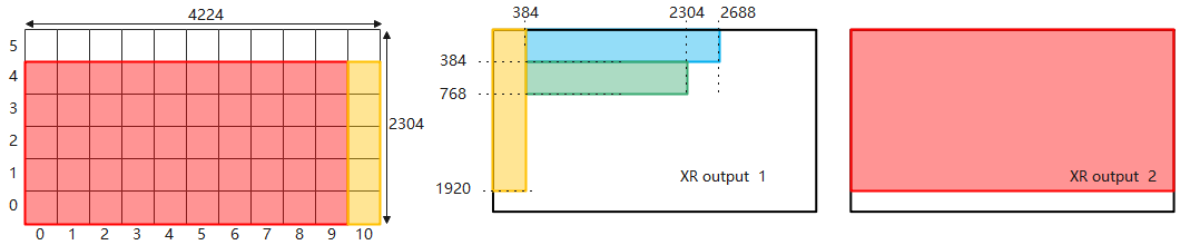
Consider an LED wall with 11 × 6 panels. If each panel has a resolution of 384 × 384 pixels, the total wall resolution would be 4224 × 2304 pixels. This exceeds the size of UHD.
For larger LED walls with resolutions exceeding a single Pixotope output, you have 2 options:
Option 1: Scale to Fit
-
Allows you to use a single output but sacrifices resolution quality
-
Can work well for testing or demonstrations but may not be ideal for production
-
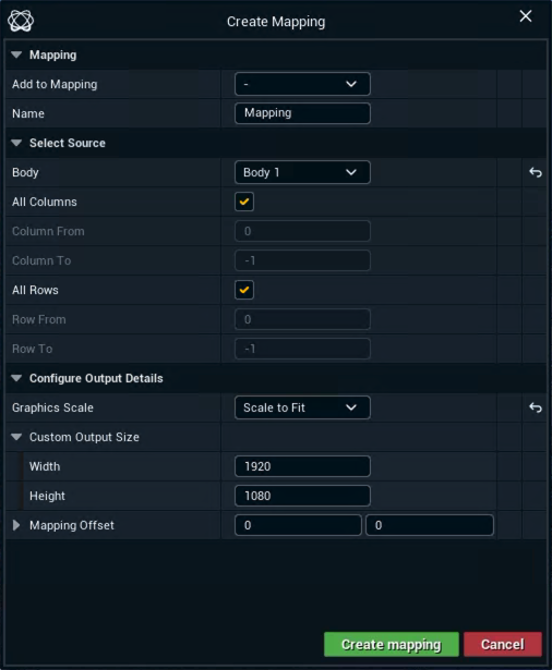
Open the Details panel of the Digital Twin XR Actor
-
Click "Create Single Mapping"
-
Body: Select the LED Body you want to creating a mapping for
-
Keep All Columns and All Rows selected
-
-
Add to Mapping: Leave blank (-)
-
Graphics Scale: Choose "Scale to Fit"
-
Set Width and Height of the mapping
-
-
Click "Create mapping"
Verify output
After creating the mapping, your XR output will display the texture with the following characteristics:
-
The XR texture takes up the entire output image
-
It reduces the XR engines at the cost of resolution loss
-
In our example we lost 14.77% resolution
-
-
Depending on the aspect ratio difference, the output image can look squeezed compare to the pixel perfect output
-
Don’t worry! The texture will be stretched back to the normal size when displayed on the LED wall
-
Option 2: Pixel Perfect with Multiple Outputs
For best quality
-
Divide your LED body into sections that can each fit within an output
For optimal performance
-
Distribute pixels evenly across outputs to balance rendering load
-
Uneven distribution can cause frame drops on heavily loaded machines
-
Note: This can be ignored if all outputs come from the same machine
-
Manual division
Example division

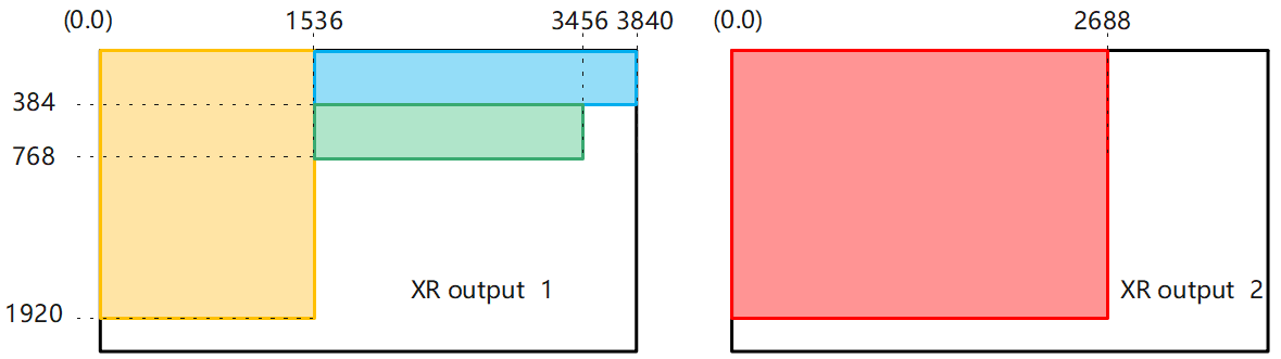
Example mapping layout
Alternative mapping layout
You can also make pixel perfect mappings in other layouts.
OR
For every single section, it starts with opening the Create Single Mapping dialog
-
Open the Details panel of the Digital Twin XR Actor
-
Click "Create Single Mapping"
-
Add to Mapping: Leave blank (-) for the first section
-
For the next sections, select the mapping it should be added to

-
-
Body: Select the LED Body you want to create a mapping for
-
Set the columns, rows and offset based on your section layout
|
Mapping |
|
Columns |
Rows |
Offset x |
Offset y |
|---|---|---|---|---|---|
|
Mapping 1 |
Section 1 (red) |
0-6 |
0-4 |
0 |
0 |
|
Mapping 2 |
Section 2 (yellow) |
7-10 |
0-4 |
0 |
0 |
|
Section 3 (blue) |
0-5 |
5-5 |
1536 |
0 |
|
|
Section 4 (green) |
6-10 |
5-5 |
1536 |
384 |
-
Graphics Scale: Choose "Pixel Perfect"
-
Click "Create mapping"
-
Repeat for each section
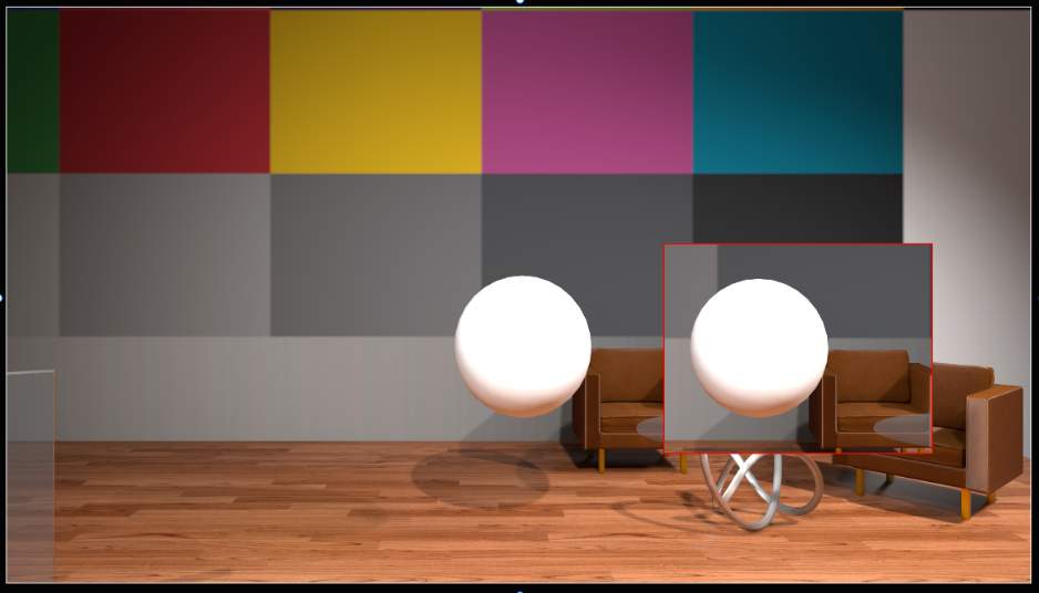
Now we have both mappings with the XR texture. Let’s see how they look.
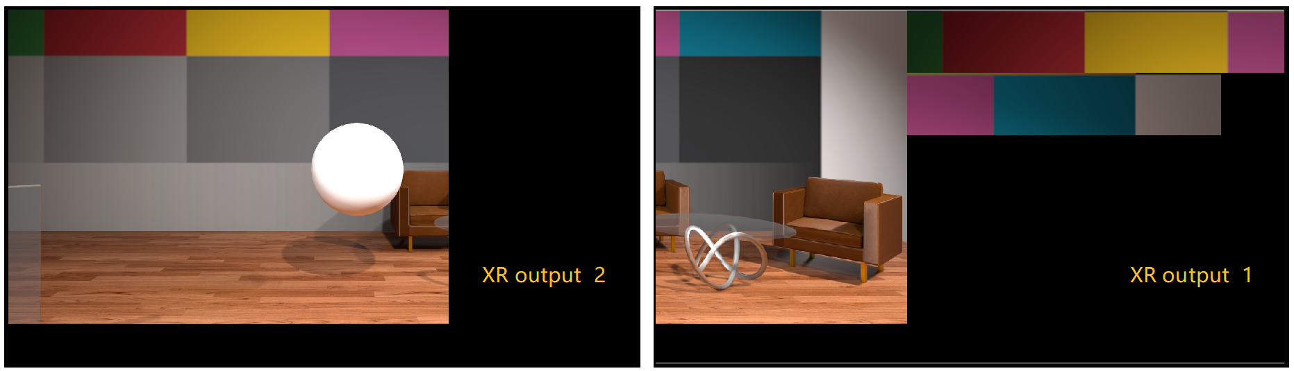
Remember to correctly position and crop each part on the LED processor.
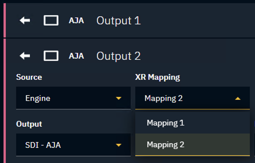
Route outputs
-
In Director: Go to SETUP > Configure > Routing
-
Select the correct mapping for each machine using the XR Mapping dropdown
Make sure that the machine has an XR render group tag.
Learn more about Render, feature and custom groups - AR, VS, AR+VS, XR
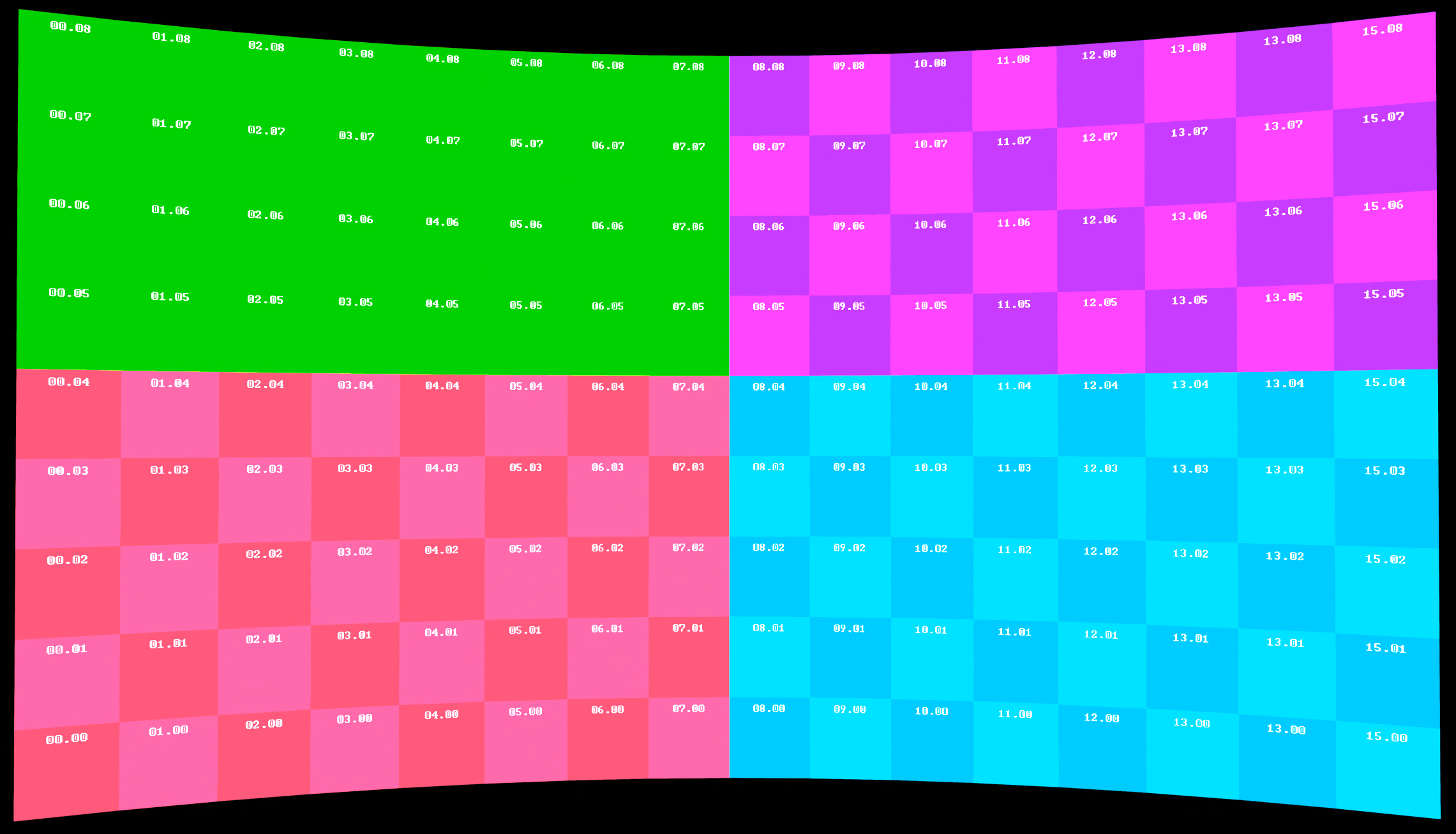
Identify your mappings
To check that your mappings have been setup and output correctly.
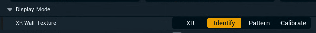
In Editor
-
Expand Display Mode
-
Choose "Identify" for the XR Wall Texture
In Director
-
Go to PRODUCTION > XR > General
-
Choose "Identify" for the Display mode for digital/manual twin
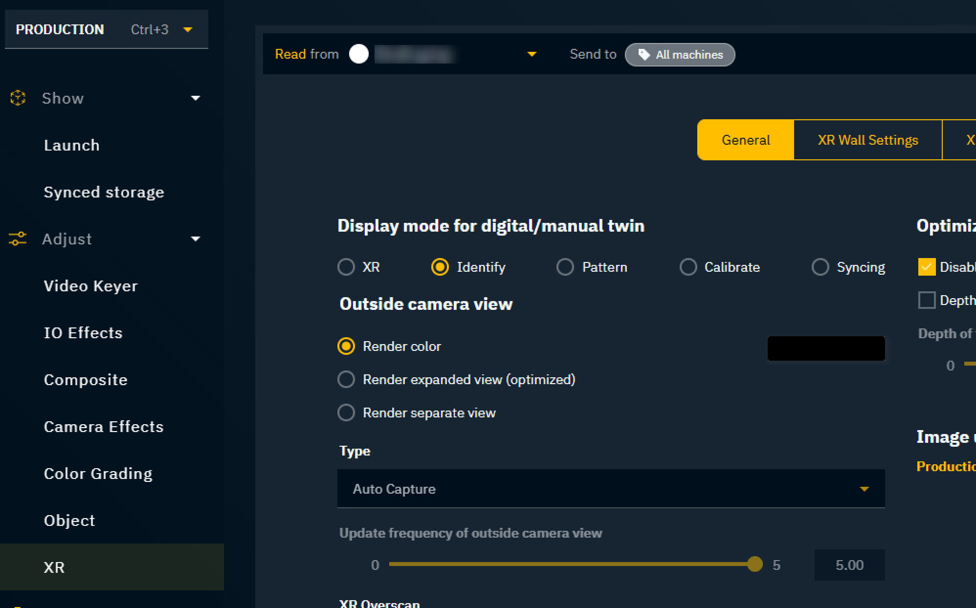
Be sure to read from the XR machine to enable the settings in the Production page.